Multi-Bit CDC Synchronizers
1. Introduction
Part 3 covered single-bit crossings, i.e. XPM_CDC_SINGLE, XPM_CDC_PULSE, the two reset XPMs, and the manual 2-FF synchronizer. Those primitives only work for one bit at a time. As soon as you have a bus crossing between domains, the same techniques applied per bit are not enough, and applying them anyway is one of the most common ways CDC bugs get into hardware.
This part is about why a per-bit synchronizer fails on a bus, the decision tree from UG949 Figure 87 for picking a multi-bit primitive, and the four XPMs that cover the multi-bit cases, i.e. XPM_CDC_ARRAY_SINGLE, XPM_CDC_GRAY, XPM_CDC_HANDSHAKE, and XPM_FIFO_ASYNC.
2. Why a Per-Bit Synchronizer Fails on a Bus
There are two independent failure modes. Either one is enough to corrupt the data, and they often happen together.
2.1 Skew Between Bits at the Synchronizer Input
Each bit of the bus is its own net from the source register to the first synchronizer flip-flop in the destination domain. Routing delays are not equal. With an N-bit bus, you get N different arrival times at the destination FFs.
If the source value transitions close to a destination clock edge, fast bits arrive before the edge and slow bits arrive after it. The synchronizers capture a mix, i.e. some bits from the new value, some from the old. The destination sees a transient value that was never present at the source.
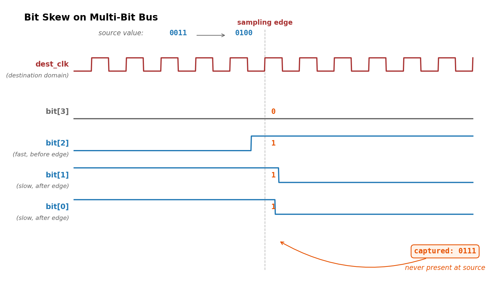
Figure 1: Bit skew on multi-bit bus
This is not a metastability problem. It happens even when every individual bit is timed cleanly. The synchronizer chain on each bit is irrelevant here, because the corruption is at the input of the chain, before any metastability resolution starts.
2.2 Independent Metastability Resolution
Now assume routing is perfect and all bits arrive at their first synchronizer FF at exactly the same instant. The source value is transitioning at the destination edge, so each first-stage FF goes metastable.
Metastability does not resolve at a fixed time. Each FF resolves independently, and the direction it resolves to is biased by where in the transition the clock landed but is not deterministic. Two adjacent bits sampling the same transition can resolve to different sides of it.
Example: the source goes from 0011 to 0100. All four bits go metastable in the destination FFs at the same clock edge. After one cycle, bit 2 has resolved to its new value (1) and the others have resolved to their old values (0). The destination domain sees 0100 as 0000 first, then 0100 on the next cycle. A receiver that latches on the first edge gets a value the source never produced.
The number of synchronizer stages does not fix this. Adding more stages reduces the probability that metastability persists, but it does not coordinate the resolution of separate FFs.
2.3 The Underlying Rule
A multi-bit value has a relationship between its bits, i.e. bit positions encode a single number, a pointer, a state. That relationship has to be preserved across the crossing. Independent per-bit synchronizers do not preserve it. You either need to encode the data so per-bit corruption is harmless (Gray code), or you need a control signal that tells the destination when the bus is safe to sample (handshake, FIFO).
3. The Multi-Bit CDC Decision Tree
UG949 Figure 87 walks through the choice. Four questions, four primitives at the leaves:
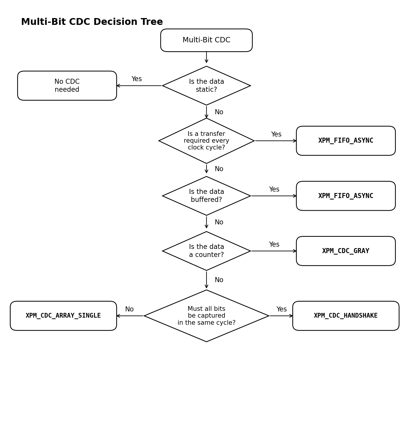
Figure 2: Multi-bit CDC decision tree
- Is the data static? If the bus is set once at startup and never changes again, no synchronizer is needed.
- Does it transfer every clock cycle, or is the data buffered? Use
XPM_FIFO_ASYNC. A FIFO is the only multi-bit primitive that keeps up with a continuous-rate stream. - Is it a counter? Use
XPM_CDC_GRAY. Gray coding turns the multi-bit problem into a single-bit problem at a time. - Must all bits land in the same destination cycle?
- No, i.e. the bits are independent. Use
XPM_CDC_ARRAY_SINGLE. - Yes, i.e. the bits are related but not Gray-coded. Use
XPM_CDC_HANDSHAKE.
- No, i.e. the bits are independent. Use
The next four sections cover each leaf in detail.
4. Static Data
If a bus is set once during configuration and never changes during operation, there is no transition for a destination FF to sample mid-edge. Metastability and skew cannot corrupt a value that is constant, so no synchronizer is needed.
A single FF in the destination domain is enough to register the value. The risk with this branch is the word “static” in practice. A configuration register that is rewritten on a mode change is not static. If there is any operating condition under which the bus changes while the destination is using it, treat it as a regular multi-bit crossing.
5. XPM_CDC_ARRAY_SINGLE
For an array of bits where each bit is independent of the others. Internally it is N parallel single-bit synchronizers, the same structure as XPM_CDC_SINGLE repeated WIDTH times. The XPM does not coordinate resolution between bits, so the bus value sampled in any given destination cycle may be a mix of recent source values.
The only reason this is safe is that the bits do not encode anything jointly. If bit 0 is “fan_enable” and bit 1 is “led_blink_mode”, neither bit’s correctness depends on the other being captured in the same cycle.
When it fits: static-ish configuration registers, status flags, mode bits. A common pattern is a software-written control register with a few independent fields, where each field reaches steady state long before any consumer reads it.
When it does not fit: anything where the bits encode a single value (pointer, address, count, encoded state). Use XPM_CDC_GRAY or XPM_CDC_HANDSHAKE instead.
5.1 Stability Requirement
UG974 spec: the input must be sampled by the destination clock two or more times. With DEST_SYNC_FF = N, you need the source to hold each value stable for at least N destination clock periods to guarantee every bit propagates through the chain to the same value. In practice this means the slowest source-side update rate must be much lower than the destination clock, i.e. exactly the configuration-register use case.
If the source updates faster than the destination can sample twice, some bits will be skipped entirely. XPM_CDC_ARRAY_SINGLE is not for that. Use a FIFO or a handshake.
5.2 SRC_INPUT_REG
Same parameter as XPM_CDC_SINGLE. Set to 1 when the input is driven by combinational logic, so the macro inserts a register clocked by src_clk and the first synchronizer FF only sees registered, glitch-free data. Set to 0 when the input is already the Q output of a flip-flop running on src_clk. src_clk only needs to be wired in when this parameter is 1.
// xpm_cdc_array_single: Single-bit Array Synchronizer
// Xilinx Parameterized Macro, version 2025.2

xpm_cdc_array_single #(
   .DEST_SYNC_FF(4),    // DECIMAL; range: 2-10
   .INIT_SYNC_FF(0),    // DECIMAL; 0=disable simulation init values, 1=enable simulation init values
   .SIM_ASSERT_CHK(0),  // DECIMAL; 0=disable simulation messages, 1=enable simulation messages
   .SRC_INPUT_REG(1),   // DECIMAL; 0=do not register input, 1=register input
   .WIDTH(2)            // DECIMAL; range: 1-1024
)
xpm_cdc_array_single_inst (
   .dest_out(dest_out), // WIDTH-bit output: src_in synchronized to the destination clock domain.
   .dest_clk(dest_clk), // 1-bit input: Clock signal for the destination clock domain.
   .src_clk(src_clk),   // 1-bit input: optional; required when SRC_INPUT_REG = 1
   .src_in(src_in)      // WIDTH-bit input: Input single-bit array to be synchronized.
);

// End of xpm_cdc_array_single_inst instantiation
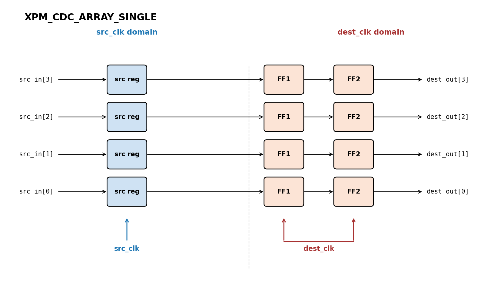
Figure 3: XPM_CDC_ARRAY_SINGLE block diagram
6. XPM_CDC_GRAY
For a binary value that only ever increments or decrements by one. The macro encodes the input to Gray code, synchronizes the Gray-coded bus through per-bit synchronizers, then decodes back to binary in the destination domain.
6.1 Why Gray Code Works for This
In binary, a counter step like 0111 to 1000 flips four bits at once. Per-bit synchronizers on that transition can produce any of the 16 intermediate values. In Gray code, every increment changes exactly one bit. So at any sampling instant, the destination either captures the old Gray value, the new Gray value, or a value that differs from both by at most one bit. That intermediate value, decoded back to binary, is always either the old or the new count. There is no way to sample a corrupted value that the source never produced.
This guarantee depends entirely on the +/-1 increment rule. If the source value can jump by more than one (a parallel load, a reset to a non-zero value, a mode-driven reseed), more than one bit changes at once and the Gray-code property is gone. Use XPM_CDC_HANDSHAKE for those cases.
6.2 The Pointer-Width Convention
The most common use of XPM_CDC_GRAY is FIFO read and write pointers across the async clock boundary. For a FIFO of depth 2^N, the pointers are sized N+1 bits, i.e. one extra bit beyond what’s needed to address the memory. The extra bit lets the FIFO logic distinguish empty (wr_ptr == rd_ptr) from full (wr_ptr == rd_ptr with the MSB inverted). When you wire those pointers through XPM_CDC_GRAY, set WIDTH = N+1 to match.
This is a pointer convention from the FIFO design, not a property of the XPM. The XPM just synchronizes whatever WIDTH you give it. If you are not building an async FIFO by hand, you do not need the extra bit.
6.3 REG_OUTPUT
By default, dest_out_bin is combinational off the destination-side decode logic. Set REG_OUTPUT = 1 to add a register stage, which gives a clean registered output at the cost of one extra cycle of latency. Use it when downstream logic has a tight setup window or you want the output isolated from the decode path.
// xpm_cdc_gray: Synchronizer via Gray Encoding
// Xilinx Parameterized Macro, version 2025.2

xpm_cdc_gray #(
   .DEST_SYNC_FF(4),               // DECIMAL; range: 2-10
   .INIT_SYNC_FF(0),               // DECIMAL; 0=disable simulation init values, 1=enable simulation init values
   .REG_OUTPUT(0),                 // DECIMAL; 0=disable registered output, 1=enable registered output
   .SIM_ASSERT_CHK(0),             // DECIMAL; 0=disable simulation messages, 1=enable simulation messages
   .SIM_LOSSLESS_GRAY_CHK(0),      // DECIMAL; 0=disable lossless check, 1=enable lossless check
   .WIDTH(2)                       // DECIMAL; range: 2-32
)
xpm_cdc_gray_inst (
   .dest_out_bin(dest_out_bin),    // WIDTH-bit output: synchronized binary output.
   .dest_clk(dest_clk),            // 1-bit input: Destination clock.
   .src_clk(src_clk),              // 1-bit input: Source clock.
   .src_in_bin(src_in_bin)         // WIDTH-bit input: Binary input bus to synchronize.
);

// End of xpm_cdc_gray_inst instantiation
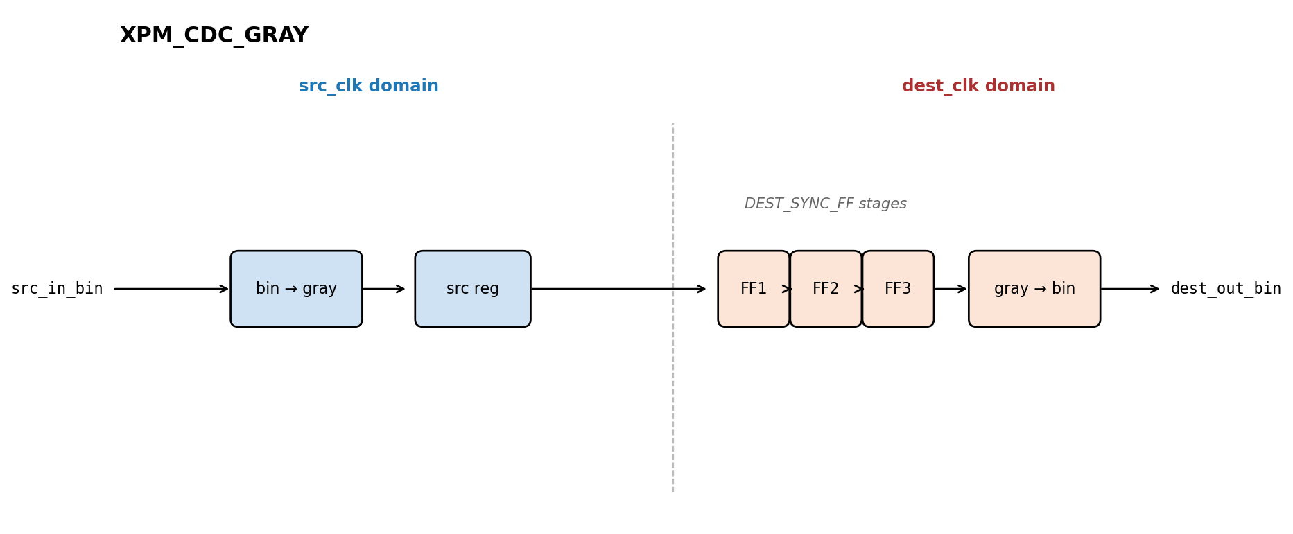
Figure 4: XPM_CDC_GRAY block diagram
7. XPM_CDC_HANDSHAKE
For a multi-bit bus that is not Gray-coded and where every bit must be captured together in the destination domain. The bus is held stable while a control bit (src_send) crosses, the destination uses the synchronized control bit (dest_req) as a qualifier to latch the data, and an acknowledgement (dest_ack to src_rcv) tells the source it can move on.
The data path itself is a plain multi-bit register. There are no synchronizers on the data lines. Only the src_send and dest_ack control bits are synchronized. The data is safe because it is held stable for the entire round-trip, so by the time the destination latches it, every bit is settled and the skew between bits no longer matters.
7.1 Ports
| Port | Direction | Description |
|---|---|---|
src_clk |
input | Source clock |
src_in[WIDTH-1:0] |
input | Data to transfer |
src_send |
input | Source asserts to start a transfer |
src_rcv |
output | Pulses when destination has captured the data |
dest_clk |
input | Destination clock |
dest_out[WIDTH-1:0] |
output | Synchronized data |
dest_req |
output | High when dest_out is valid |
dest_ack |
input | Destination asserts to acknowledge capture (external mode only) |
7.2 Internal vs External Handshake
DEST_EXT_HSK selects between two modes:
-
DEST_EXT_HSK = 0(Internal): The destination side of the macro generatesdest_ackautomatically once it has registered the data. The user does not drivedest_ack. Simpler to wire up, but the macro acknowledges as soon as the data is latched intodest_out, so there is no way to wait until downstream logic has actually consumed it. -
DEST_EXT_HSK = 1(External, default): The user drivesdest_ackfrom the destination logic. This lets the destination delay the acknowledge until it is genuinely ready for a new value, which is the right choice when the data feeds a state machine that may need multiple cycles to process each transfer.
7.3 Transfer Sequence
The full handshake is four steps. Source must wait through all of them before issuing the next src_send:
- Source places data on
src_inand assertssrc_send. src_sendpropagates through theSRC_SYNC_FF-deep destination synchronizer and emerges asdest_req.- Destination latches
dest_outwhiledest_reqis high. In external mode, destination then assertsdest_ack. dest_ackpropagates through theDEST_SYNC_FF-deep source synchronizer and emerges assrc_rcv.
Source deasserts src_send after seeing src_rcv. Only then is the macro ready for another transfer.
7.4 Throughput
The full round-trip is roughly SRC_SYNC_FF + DEST_SYNC_FF clock cycles (plus destination processing time in external mode). With defaults of 4 each, that is at least 8 cycles per word. XPM_CDC_HANDSHAKE is for low-rate, integrity-critical transfers, i.e. control words, command packets, configuration updates that are not static. For sustained data streams, use a FIFO.
// xpm_cdc_handshake: Bus Synchronizer with Full Handshake
// Xilinx Parameterized Macro, version 2024.2

xpm_cdc_handshake #(
   .DEST_EXT_HSK(1),     // DECIMAL; 0=internal handshake, 1=external handshake
   .DEST_SYNC_FF(4),     // DECIMAL; range: 2-10
   .INIT_SYNC_FF(0),     // DECIMAL; 0=disable simulation init values, 1=enable simulation init values
   .SIM_ASSERT_CHK(0),   // DECIMAL; 0=disable simulation messages, 1=enable simulation messages
   .SRC_SYNC_FF(4),      // DECIMAL; range: 2-10
   .WIDTH(8)             // DECIMAL; range: 1-1024
)
xpm_cdc_handshake_inst (
   .dest_out(dest_out),  // WIDTH-bit output: data latched from src_in when dest_req is high.
   .dest_req(dest_req),  // 1-bit output: indicates dest_out is valid.
   .src_rcv(src_rcv),    // 1-bit output: pulses when destination has captured the data.
   .dest_ack(dest_ack),  // 1-bit input: destination ack (only used when DEST_EXT_HSK = 1).
   .dest_clk(dest_clk),  // 1-bit input: Destination clock.
   .src_clk(src_clk),    // 1-bit input: Source clock.
   .src_in(src_in),      // WIDTH-bit input: data to be transferred to destination domain.
   .src_send(src_send)   // 1-bit input: assert (and hold) to initiate a transfer.
);

// End of xpm_cdc_handshake_inst instantiation
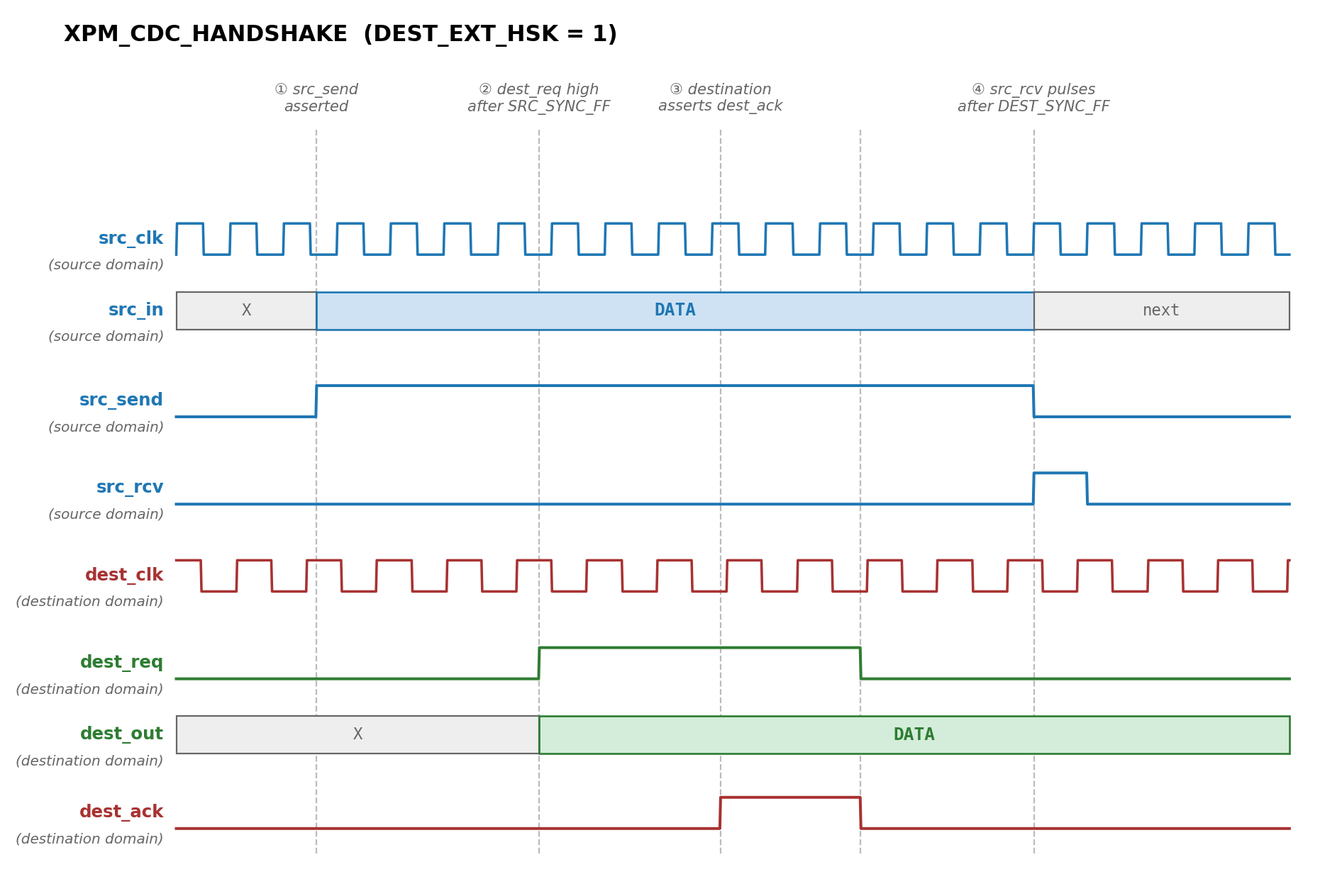
Figure 5: XPM_CDC_HANDSHAKE waveform
Note:
XPM_CDC_HANDSHAKEis missing from UG974 v2025.2. The macro is referenced in the body of the document but has no entry of its own. The macro itself ships with Vivado, i.e. it is inxpm_cdc.svand the VHDL component declarations. The port and parameter list above is from the Vivado source. The AMD docs portal also has a current entry for it.
8. XPM_FIFO_ASYNC
A two-clock FIFO. Write side is in the source domain (wr_clk, wr_en, din, full), read side is in the destination domain (rd_clk, rd_en, dout, empty). Internally it uses dual-port memory plus Gray-coded read/write pointers that get synchronized across the clock boundary, i.e. the same XPM_CDC_GRAY technique from earlier, but wrapped in a primitive that handles the addressing, full/empty logic, and reset sequencing.
This is the right choice for two situations:
- Sustained-rate data: anything where transfers happen on a per-cycle basis, i.e. a continuous data stream from one clock domain to another.
- Buffered data: when source and destination are bursty and you need to absorb rate mismatches.
Important: this is XPM_FIFO_ASYNC, not XPM_FIFO_SYNC. XPM_FIFO_SYNC is a single-clock FIFO and does not perform CDC. XPM_FIFO_ASYNC is the multi-clock version, and is the one named in the UG949 decision tree.
8.1 Reset Behavior
The reset rules are not casual:
rstis synchronous towr_clk. Both clocks must be running and stable before reset is released.- After issuing
rst, wait forwr_rst_busyto deassert before issuing anywr_en, and wait forrd_rst_busyto deassert before issuing anyrd_en. wr_enmust be held low whilewr_rst_busyis high.rd_enmust be held low whilerd_rst_busyis high.- Do not issue another
rstwhile either busy signal is still high.
These rules exist because the reset itself has to propagate across the clock domains internally. Violating them produces undefined FIFO state, not a clean error.
8.2 READ_MODE: Standard vs. FWFT
std: Data appears ondoutonly afterrd_enis asserted, with latency set byFIFO_READ_LATENCY(range 0 to 10).fwft(First-Word Fall Through): The first word is presented ondoutautomatically when the FIFO becomes non-empty.data_validindicates whendoutholds a valid word.FIFO_READ_LATENCYmust be 0 in this mode.
FWFT is convenient for reading into a state machine that wants to peek at the first word before committing to a read. Standard mode is lower-latency for back-to-back reads when you know you want the data.
8.3 USE_ADV_FEATURES
A bit-encoded string parameter (default "0707") that enables optional output flags, i.e. overflow, prog_full, wr_data_count, almost_full, wr_ack, underflow, prog_empty, rd_data_count, almost_empty, data_valid. Each bit position enables one signal. The defaults give you the common ones (overflow, underflow, prog_full, prog_empty, both data counts) and skip the rarely used ones. Set unused output signals’ enable bits to 0 if you care about resource usage, since synthesis trims the logic.
8.4 CDC_SYNC_STAGES and RELATED_CLOCKS
CDC_SYNC_STAGES (default 2, range 2 to 8) is the DEST_SYNC_FF equivalent for the internal pointer synchronizers. Same MTBF tradeoff as the standalone XPM CDC primitives.
RELATED_CLOCKS should be 0 (default) for fully asynchronous clocks. Set to 1 only when wr_clk and rd_clk are generated from the same primary clock with different ratios. The macro can then take advantage of the known ratio to reduce internal margin.
// xpm_fifo_async: Asynchronous FIFO
// Xilinx Parameterized Macro, version 2025.2

xpm_fifo_async #(
   .CDC_SYNC_STAGES(2),
   .FIFO_MEMORY_TYPE("auto"),
   .FIFO_READ_LATENCY(1),
   .FIFO_WRITE_DEPTH(2048),
   .READ_DATA_WIDTH(32),
   .READ_MODE("std"),
   .RELATED_CLOCKS(0),
   .USE_ADV_FEATURES("0707"),
   .WRITE_DATA_WIDTH(32),
   .WR_DATA_COUNT_WIDTH(12),
   .RD_DATA_COUNT_WIDTH(12)
)
xpm_fifo_async_inst (
   .dout(dout),
   .empty(empty),
   .full(full),
   .rd_data_count(rd_data_count),
   .rd_rst_busy(rd_rst_busy),
   .wr_data_count(wr_data_count),
   .wr_rst_busy(wr_rst_busy),
   .din(din),
   .rd_clk(rd_clk),
   .rd_en(rd_en),
   .rst(rst),
   .wr_clk(wr_clk),
   .wr_en(wr_en)
);

// End of xpm_fifo_async_inst instantiation
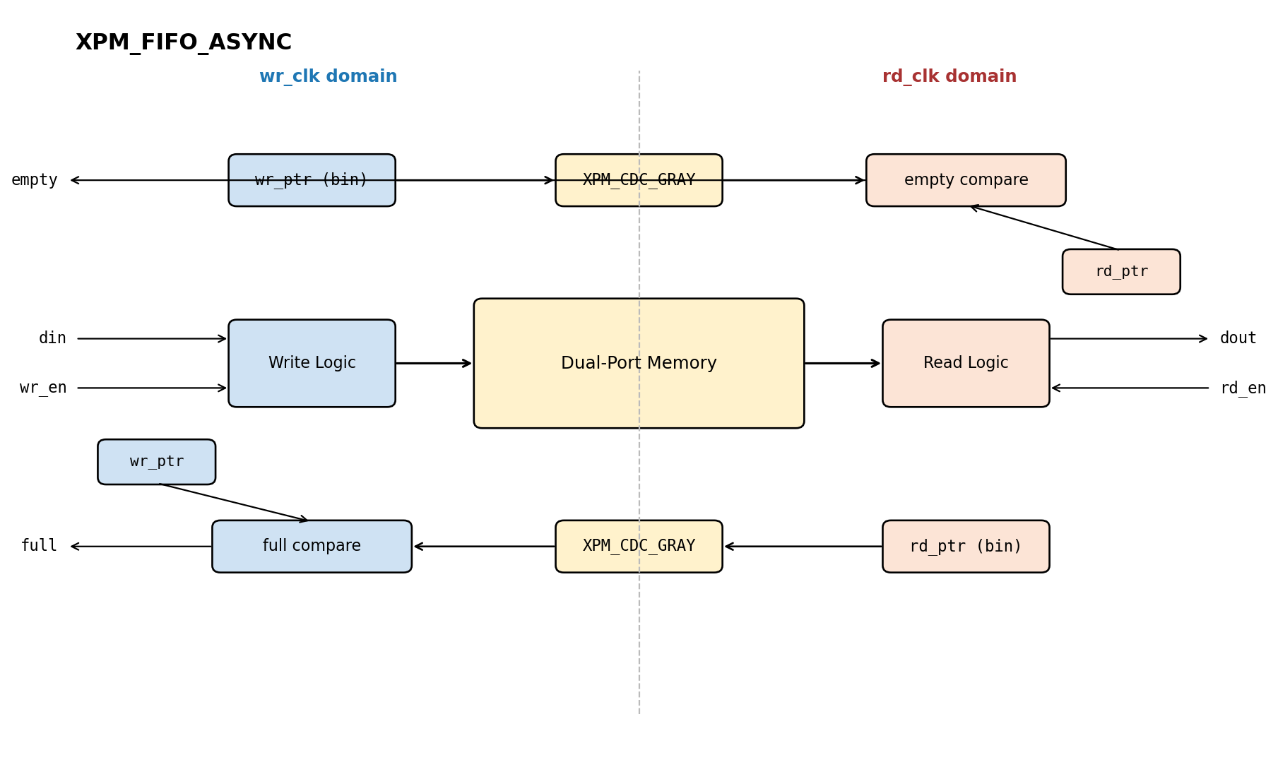
Figure 6: XPM_FIFO_ASYNC block diagram
9. Conclusion
For a multi-bit crossing, asking “is this safe?” is the wrong question. Ask “what is the relationship between the bits, and what coordinates them?”
- Static, no synchronizer needed.
- Independent bits:
XPM_CDC_ARRAY_SINGLE, but only for slow-changing data. - Counter:
XPM_CDC_GRAY, because the +/-1 rule reduces the multi-bit problem to a single-bit problem. - Related bits, low rate:
XPM_CDC_HANDSHAKE, with the data held stable while a synchronized control bit qualifies it. - Related bits, high rate or buffered:
XPM_FIFO_ASYNC, which isXPM_CDC_GRAYplus a memory plus the addressing logic.
The decision tree from UG949 is short on purpose. Most real bugs in multi-bit CDC come from picking the wrong leaf, usually XPM_CDC_ARRAY_SINGLE for data that has a relationship between bits, or a manual per-bit synchronizer that does not even appear in the tree. If you cannot point at a single leaf and say “this one, because the data matches its assumptions,” the design is not yet ready for synthesis.
Series: Clock Domain Crossing (CDC)
Part Topic Part 1 Clock Types, Metastability & the Clock Interaction Report Part 2 The report_cdc Report Part 3 Single-Bit CDC Synchronizers Part 4 (this post) Multi-Bit CDC Synchronizers