The report_cdc Report
1. Introduction
In Part 1, we used the clock interaction report to understand the clock pairs in a design — which ones are synchronous, which are asynchronous, and which crossings are already constrained. That report works at the level of clock pairs. It tells you that a crossing exists between clk_a and clk_b, but it does not tell you what is crossing, whether those crossings are properly synchronized, or what kind of synchronization structure is present.
report_cdc is the next step. It operates at the level of individual paths. For every signal that crosses a clock domain boundary, it identifies the source and destination flip-flops, determines what synchronization structure — if any — is present, and flags anything that looks unsafe. This is the tool you use once you know which clock pairs need attention.
2. Running report_cdc
report_cdc can be run from the Tcl console or from the Reports menu in an open synthesized or implemented design.
From the Tcl console:
report_cdc -file cdc_report.txt
From the GUI, go to Reports → Report CDC. This opens the dialog shown below.
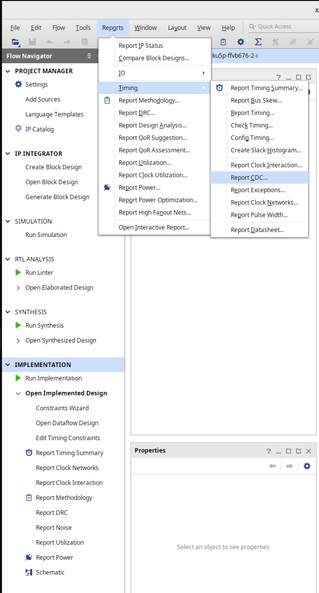
Figure 1: Report CDC dialog
The -file option writes the report to a file. Without it, the report appears only in the Vivado console. Running it after implementation gives more accurate results since routing delays are known, but running it after synthesis is also valid and is the more common point in the flow.
3. Report Structure
The report has two main sections: a Summary and a Details table.
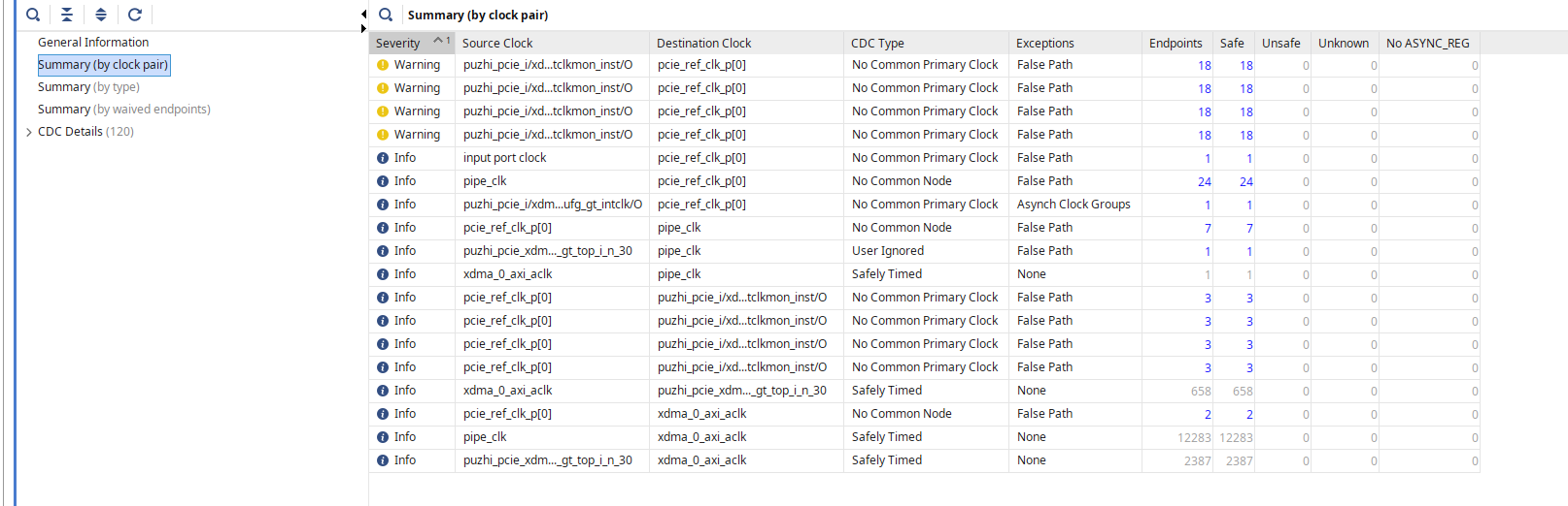
Figure 2: Full report_cdc output
The Summary gives you an aggregate view: how many crossings of each type exist and at what severity. The Details table lists every individual crossing with its source, destination, type, and any timing constraints that have been applied.
4. The Summary Section
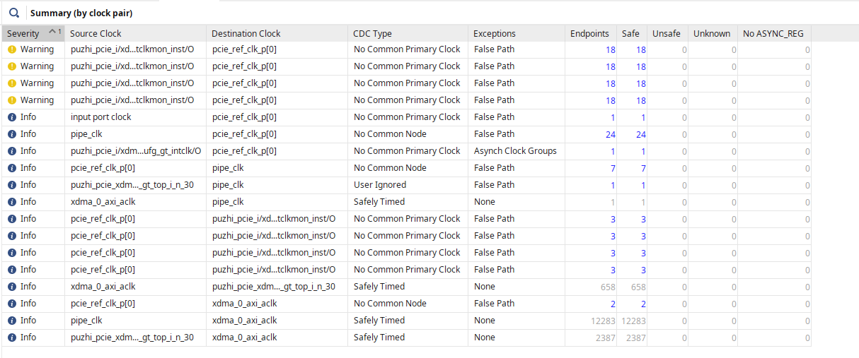
Figure 3: Summary section of report_cdc
The Summary groups all detected CDC crossings by CDC type and severity. Each row is one category of crossing. The columns show the count of crossings in that category.
The purpose of this table is to quickly orient you before diving into individual paths. If you have 3 Critical Warnings in one category and 47 in another, you know where to focus first. If the same CDC type keeps appearing across many clock pairs, there may be a systematic issue in the design rather than isolated mistakes.
The severity column follows three levels:
Critical Warning: A signal crosses a clock domain boundary with no recognized synchronization structure, or with a structure that is known to be unreliable. These are the crossings most likely to cause hardware failures. Every Critical Warning needs to be resolved, either by adding proper synchronization or by applying an appropriate constraint after confirming the path is already safe.
Warning: A synchronization structure was detected, but something about it is suspicious. Most commonly this is a multi-bit bus where each bit has its own synchronizer but there is no mechanism to ensure all bits are captured in the same clock cycle. The synchronizers themselves are fine, but the multi-bit data can still be corrupted.
Info: The crossing has a recognized synchronization structure and Vivado is satisfied it is handled correctly. Info entries do not require action, but it is worth reviewing them occasionally to make sure the synchronizer is where you actually think it is.
5. The Details Table
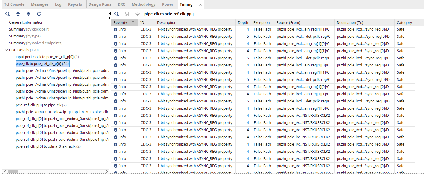
Figure 4: Details table
Each row in the Details table represents a single crossing from one flip-flop to another. The columns are:
5.1 Severity
Same three levels as the Summary. Repeated here so you can sort or filter the table by severity and work top-down through the Critical Warnings.
5.2 CDC Type
The category of CDC crossing that Vivado has identified. This is explained in full in the next section.
5.3 From Clock / To Clock
The source and destination clock domains. These are the clock names as defined in your constraints — the same names that appear in the clock interaction report. Matching these columns against the clock interaction report is how you cross-reference the two reports.
Example: A crossing shows From Clock: clk_100 and To Clock: clk_eth. If you look at the clock interaction report and that pair shows red (Timed, Unsafe), then you know these two clocks are asynchronous and any synchronization issue on this path is a real hardware risk, not just a constraint formality.
5.4 From Endpoint / To Endpoint
The full hierarchical path to the source and destination flip-flops. This is the information you need to locate the crossing in the design. Copy either endpoint path, paste it into the Tcl console with get_cells, and use select_objects to highlight it in the schematic or device view.
select_objects [get_cells data_path/sync_reg[0]]
The source flip-flop (From Endpoint) is the register whose output is crossing the clock boundary. The destination flip-flop (To Endpoint) is the first register in the receiving domain — or the first stage of the synchronizer if one is present.
5.5 Exception
Any timing constraint applied to this crossing. Common values are:
- None — No constraint has been applied. For a properly synchronized single-bit crossing you should see a
set_false_pathhere. If the field is empty and the severity is Critical Warning, the crossing is both unsynchronized and unconstrained. - False Path — A
set_false_pathconstraint is applied. The path is excluded from timing analysis. - Max Delay Datapath Only — A
set_max_delay -datapath_onlyconstraint is applied, bounding the path delay without using clock timing for the check. Used for multi-bit buses crossing synchronously under a valid protocol.
The Exception column tells you whether a constraint has been applied but not whether that constraint is correct. A set_false_path on a multi-bit bus that needs bounded skew is a constraint, but it is the wrong one. Reviewing what the constraint does and whether it is appropriate for the CDC type is your job, not the tool’s.
6. CDC Types
The CDC Type column tells you what Vivado found at each crossing. The types and their severities are:
No Synchronizer: Critical Warning. A signal crosses directly from one clock domain to another with no synchronization structure present.
Single Bit Synchronizer: Info. A properly recognized 2-FF chain clocked by the destination clock. This is the correct structure for a single-bit crossing.
Multi-Bit Synchronizer: Warning. Each bit of a bus has its own synchronizer, but there is no guarantee all bits resolve in the same clock cycle. Can corrupt multi-bit data.
Multi-Stage Synchronizer: Info. A synchronizer with more than two flip-flops in the chain. Not a problem — shows as Info.
Combinatorial: Warning. Combinatorial logic sits between the source flip-flop and the first synchronizer stage, introducing glitch risk before the synchronizer captures the signal.
Shift Register: Warning. The synchronizer chain was inferred as an SRL primitive instead of individual flip-flops. SRL timing properties do not meet the MTBF assumptions of a flip-flop synchronizer. Fixed with the (* ASYNC_REG = "TRUE" *) attribute.
Fan-out: Warning. A single CDC source drives a large number of destinations, creating routing skew that may cause different registers to capture the value in different cycles.
Each of these types will be covered in future blogs in the series.
7. Acting on the Report
The order of operations when working through a report_cdc output:
Start with Critical Warnings. Every No Synchronizer entry is a real hardware risk. For each one, find the source and destination paths using the endpoint columns, understand the data being transferred (single bit, multi-bit, control vs. data), and add the appropriate synchronization structure.
Review Warnings next. Multi-Bit Synchronizer entries are common in designs that started with single-bit synchronizers and were later expanded to buses. Evaluate whether the data being transferred requires coherency across bits. Gray-coded values are safe with individual bit synchronizers. Binary values are not.
Check Combinatorial and Shift Register entries. Both of these affect a synchronizer that already exists. Add the ASYNC_REG attribute to resolve Shift Register entries. Move combinatorial logic into the source domain to resolve Combinatorial entries.
Confirm Info entries. Info entries mean Vivado is satisfied, but skimming them confirms the synchronizer is at the location you expect. If an Info entry shows a synchronizer path that you don’t recognize, trace it back — something may have been automatically inferred or inferred in the wrong place.
Use the Exception column to verify constraints. For any crossing that has been handled at the constraint level rather than with a hardware synchronizer, confirm the constraint type matches the crossing type. A single-bit crossing through a 2-FF synchronizer needs set_false_path. A gray-coded bus needs set_max_delay -datapath_only. A handshake bus needs set_max_delay -datapath_only applied to the data signals. Getting this wrong produces a green Exception column but still incorrect hardware behavior.
8. Waivers
Once a CDC crossing is reviewed and confirmed to be handled correctly, you can create a CDC waiver so that Vivado stops reporting it in future runs. This avoids having to re-examine paths you have already analyzed every time you re-run the report.
From the Tcl console:
create_waiver -type CDC -id {CDC-1} -from [get_cells src_reg] -to [get_cells dst_reg] -description "Synchronized by 2-FF chain in dst_clk domain"

Figure 10: Waiver entry in the report — waived crossings are excluded from the active CDC count and annotated in the output.
Waivers are stored in the project and persist across report runs. They are not timing constraints i.e. they do not affect analysis, only the reporting. Use them deliberately and document the reason in the -description field. A waiver with an empty or vague description is not useful if someone later needs to understand why that crossing was signed off.
9. Conclusion
The clock interaction report from Part 1 identifies which clock pairs have crossings and what their relationship is. report_cdc goes further and identifies exactly what is crossing, what structure is handling it, and where the problem is in the design hierarchy.
The Critical Warning entries from No Synchronizer are the highest priority. Warnings from Multi-Bit Synchronizer require understanding whether the data crossing needs coherency. Combinatorial and Shift Register entries require fixing the synchronizer implementation even when the synchronizer itself is present. Info entries confirm that Vivado recognizes the synchronization correctly.
Together with the clock interaction report, report_cdc gives a complete picture of all clock domain crossings in the design before a single simulation or hardware test is run. Any unresolved Critical Warning in this report is a potential source of intermittent failures in hardware that will not reproduce in simulation.
Series: Clock Domain Crossing (CDC)
Part Topic Part 1 Clock Types, Metastability & the Clock Interaction Report Part 2 (this post) The report_cdc Report Part 3 Single-Bit CDC Synchronizers