Clock Domain Crossing and Metastability in FPGAs
1. Introduction
Until now we assumed the source and destination registers share a known timing relationship, typically the same clock.
However, there are cases when we need to run our design at different clocks. This can cause problems if not carefully managed. In this series, we’ll be discussing these problems and how to mitigate them and design around them.
2. Types of Clocks
Before we start, we need to lay some groundwork. There can be different types of clocks in an FPGA design. These are:
2.1 Primary Clocks
A primary clock is a system-level clock that enters the Vivado design through an input port.
2.2 Virtual Clocks
A virtual clock is a clock object that is not physically attached to any netlist elements in the design. For example, if a signal is coming on an input port through an external clock but this clock is not entering the FPGA, then to perform timing analysis we need a way to define this signal’s clock frequency. We use virtual clocks for this.
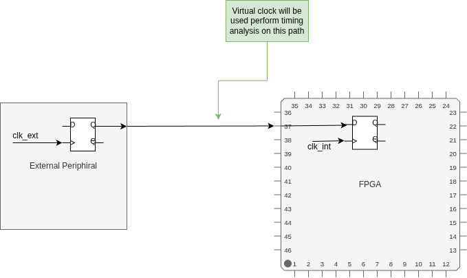
Figure 1: Virtual clock — clk_ext drives the external peripheral but does not enter the FPGA. A virtual clock is defined to represent it for timing analysis on the input path.
2.3 Generated Clocks
Generated clocks are clocks derived from a primary clock inside the design. Most commonly this is through a PLL or MMCM, but they can also come from clock dividers, BUFGCE-based gating, or any net where you explicitly define a generated clock using create_generated_clock.
3. Synchronous and Asynchronous Clocks
Clocks are considered synchronous if their phase relationship is known and deterministic, allowing static timing analysis to determine the exact launch and capture edges.
Clocks are considered asynchronous if there is no fixed phase relationship between them. This typically happens when the clocks originate from independent sources such as different crystal oscillators or independent PLLs.
4. What is Metastability?
Every flip-flop has setup and hold time requirements — data has to be stable for a set time before and after the clock edge for the output to be reliable. When these are violated, the flip-flop enters a metastable state. The output doesn’t immediately resolve to 0 or 1 — it floats somewhere in between and eventually settles, but the time it takes is unpredictable.
This is the core problem in CDC. When a signal crosses from one clock domain to another, there’s no guarantee the destination flip-flop won’t sample it right at a transition. If it does, the output is undefined for some amount of time and anything downstream sees corrupted data.
5. Why Do We Need Proper CDC?
If the source and destination clocks are both primary clocks, Vivado has no way to know their phase relationship if the clocks are derived from different sources i.e. how the positive edges of these two clocks align relative to each other as Vivado has no knowledge of their phase relationship because they are coming from an external source. Because of this, timing analysis can pass while the design still fails in hardware. This is why proper CDC techniques are necessary when asynchronous clocks are used.
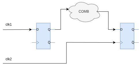
Figure 2: A CDC crossing — the source register runs on clk1, the destination register on clk2. The two clocks are independent.
For example, the phase relationship between two asynchronous clocks can look like any of these:
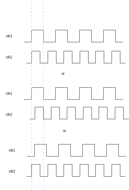
Figure 3: Possible phase relationships between two asynchronous clocks — Vivado cannot determine which one applies at runtime.
Vivado can’t determine these relations from static analysis. When it times these paths, it picks an edge alignment based on what it can infer — but since the clocks are truly asynchronous, the actual phase relationship shifts continuously at runtime. A clean timing report on these paths doesn’t mean much. Timing can still fail in hardware even with no violations reported.
6. Can’t We Just Calculate the Worst Case Timing?
In synchronous timing, Vivado knows exactly which launch edge maps to which capture edge. The relationship is fixed, so it can compute setup and hold slack for that specific edge pair. That is the whole basis of static timing analysis.
For async clocks, the capture edge can land at any offset relative to the launch edge. Including right at the moment the data is transitioning. When that happens, setup time is effectively violated. The flip-flop is sampling a signal mid-transition. That is metastability.
Example: Say your path delay is 3 ns. Data transitions 3 ns after the launch clock edge. Your capture clock is async, so over millions of cycles it will eventually fire at exactly t = 3 ns after a launch edge — right when the data is mid-transition. No timing constraint can prevent this from happening.
The natural follow-up is: can we just make the path faster or slower to avoid that alignment? No. Whatever path delay you pick, there is always a phase offset where the capture edge falls exactly at the data transition. You are not avoiding the problem, just moving it to a different phase offset. And since the clocks are async, every phase offset will eventually occur.
The deeper issue is this: timing analysis is built on the assumption that you can find the worst-case edge pair and check timing for it. For async clocks, the worst case is edges perfectly aligned — setup time = 0. No path meets timing for that. You cannot constraint your way out of it.
So the solution is not better timing constraints. It is synchronizer circuits. A synchronizer does not prevent metastability — it accepts it will happen and gives the flip-flop output time to resolve before anything downstream samples it. The MTBF calculation tells you how long you need to wait to get an acceptable failure rate. We will cover this in the next part.
7. The Clock Interaction Report
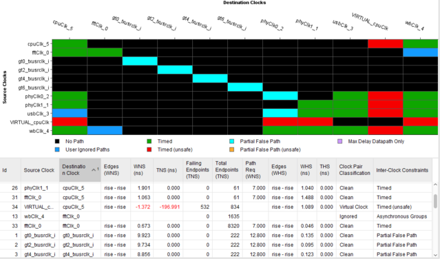
Figure 4: Vivado clock interaction report — each tile shows the timing relationship between a source and destination clock pair. Source: Vivado Design Suite User Guide: Design Analysis and Closure Techniques (UG906)
7.1 Color Meanings
Black: No Path
No timing paths exist between the source and destination clocks. Meaning there is no path in which the source register runs on one of these two clocks and the destination register on the other one.
Example: Your design has a USB clock and a PCIe clock but no data ever crosses between them. No register clocked by one ever feeds a register clocked by the other. They show up black.
Green: Timed
The clocks are synchronous. Meaning the clocks are related and Vivado can safely perform static timing analysis between them. So even though their frequency and phase can be different, there will exist a simple period ratio that Vivado knows about.
Example: clk_100 is your primary clock. You pass it through an MMCM and get clk_200. Vivado knows clk_200 is exactly 2x clk_100, so it can time paths between them properly. This pair shows green.
Dark Blue: User Ignored Paths
Paths between these clocks are excluded from timing analysis due to user constraints such as set_false_path.
Example: You have a FIFO crossing from clk_100 to clk_200, both generated from the same primary clock. You’ve handled the synchronization properly and applied set_false_path. Those paths go dark blue.
Light Blue: Partial False Path
Some paths between the synchronous source and destination clocks are ignored using constraints (like set_false_path), but not all paths. Vivado will still time the remaining unconstrained paths. This indicates that CDC has been partially managed, and you need to ensure the unconstrained paths are also handled correctly. Example: Same setup as dark blue, but you only constrained 6 of the 10 crossing paths and missed the rest. It shows light blue instead.
Red: Timed (Unsafe)
The clocks are asynchronous (they do not share a common primary clock) but Vivado is still trying to time the paths. An unexpandable period means that Vivado can’t find common integer multiple of periods of the two clock within its analysis window. Any CDC path between these clocks is unsafe regardless of what the timing report says.
Example: clk_sys comes from a crystal oscillator on one input pin, clk_eth comes from an Ethernet PHY. No shared ancestry. Any path between them is red.
Orange: Partial False Path (Unsafe)
This means the clocks are asynchronous, and some paths between them are ignored using constraints, while others are still being timed.
Example: Same as the red scenario, but you applied set_false_path to some of the crossing paths. The tile goes orange — those specific paths are excluded from timing, but the situation is still fundamentally unsafe.
Gray: Max Delay Datapath Only
All crossing paths are covered by a set_max_delay -datapath_only constraint.
To understand why this constraint exists, we start with normal setup timing:
\[\text{setup slack} = \text{capture_edge} - \text{launch_edge} - \text{clock_skew} - \text{clock_uncertainty} - \text{datapath_delay} - \text{FF_setup_time} \tag{1}\]set_max_delay -datapath_only X throws all of that out and replaces it with one check: is the combinational path delay shorter than X? Nothing else is used i.e. clock_skew, clock_uncertainity etc.
The reason path delay still matters for CDC is that assume you have a 16-bit bus crossing from clk_a to clk_b with a handshake. Bit 0 takes 1 ns through the combinational logic, bit 15 takes 7 ns. Destination clock period is 5 ns. When clk_b edge arrives, bit 0 is stable but bit 15 is still in transit. clk_b captures bit 0 from the new value and bit 15 from the old value which would result in corrupted data.
set_false_path removes all delay constraints. The router can make your 16-bit bus bits take 0.5 ns to 15 ns and Vivado will not flag it. set_max_delay -datapath_only is the middle ground which basically says I have handled the CDC myself, but still make sure all bits arrive within a bounded window.
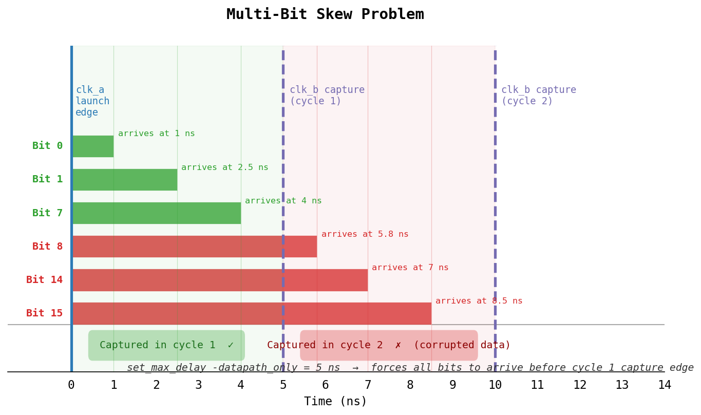
Figure 5: Multi-bit skew — bits with different combinational path delays get captured in different clock cycles, resulting in corrupted data.
When to use which:
Single-bit crossing with a synchronizer: use set_false_path. Path delay does not matter, i.e. the synchronizer handles metastability regardless of how long the path takes.
Multi-bit bus (gray code, handshake, qualified enable): use set_max_delay -datapath_only. You need all bits to land in the destination FF within the same clock cycle.
The rule of thumb: one bit means relative skew between bits cannot exist, so path delay does not affect correctness thus use set_false_path. Multiple bits that must be captured together means you need to bound their delays relative to each other hence, use set_max_delay -datapath_only.
7.2 Clock Pair Classification
This column in the picture above shows the relation between the two clocks.
Ignored
The path between these two clocks is ignored completely through user constraints.
Example: You’ve applied set_false_path -from [get_clocks clk_a] -to [get_clocks clk_b]. Vivado ignores all timing between them.
Virtual Clock
One or both clocks are virtual, so common primary clock or node checks do not apply.
Example: An ADC on your board samples data on ext_adc_clk, but that clock doesn’t enter the FPGA. You define a virtual version of it and set input delays against it. Paths referencing that virtual clock show up here.
No Common Clock
The clocks do not share a common primary clock.
Every generated clock in Vivado traces back to a primary clock. If you follow clk_a back up the clock tree and follow clk_b back up and the paths never meet, that’s No Common Clock. They are asynchronous by definition.
Example: clk_sys and clk_eth — two independent primary clocks with no shared source.
No Common Period
The clock periods cannot be reduced to a common integer ratio, so Vivado can’t find a reliable launch/capture edge pair.
To time paths between two clocks, Vivado needs to know how many cycles of clock A fit into how many cycles of clock B. Vivado tries to find the timing window (the LCM) and enumerate which launch/capture edge pairs to analyze. 10 ns and 5 ns gives an LCM of 10 ns, fine. But 7.3 ns and 10.17 ns have no clean ratio. Finding aligned edges would take thousands of cycles. Vivado has an expansion limit and gives up.
Example: A 7.3 ns and 10.17 ns clock has no clean integer relationship, so Vivado can’t find aligned edges within a usable analysis window.
No Common Node
The two clocks are synchronous, but the crossing paths do not have a common node.
When Vivado times paths between two synchronous clocks, it looks for the physical point in the netlist where their clock paths diverge i.e. the common node. Vivado measures the routing delay from that node to each destination FF, subtracts them, and gets the real skew. Without a common node there is no anchor for that calculation. The clocks may be related on paper, but Vivado cannot establish the timing from the actual routed netlist.
Example: Two generated clocks both derived from clk_sys but routed through different BUFG/MMCM instances. The primary clock is same, but the paths diverge before any common node Vivado can use for timing.
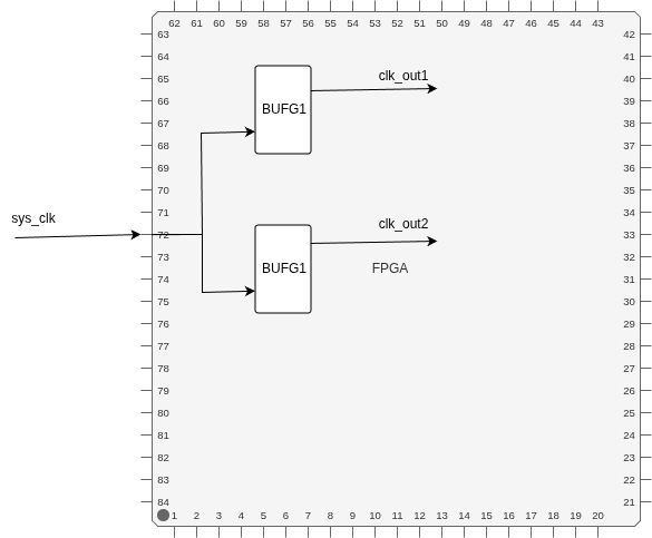
Figure 6: sys_clk fans out to two separate BUFG instances. There is no common node between clk_out1 and clk_out2 in the FPGA clock network — Vivado cannot anchor the skew calculation.
Here there is no common node in the clock network tree internal to the FPGA. Hence, the path between clk_out1 and clk_out2 will be flagged as No Common Node.
Partial Common Node
The two clocks are synchronous, but a subset of the crossing paths does not have a common node and cannot be safely timed.
Same situation as No Common Node, but only for a subset of crossing paths. Most paths between the two clocks have a traceable common node and can be timed normally. A few specific paths don’t — maybe they route through an unexpected clock buffer — and those get flagged.
Example: Two clocks both derived from the same MMCM, but one CDC path routes through a different clock buffer. That specific path loses the common node.
No Common Phase
The clocks lack a known phase relationship.
Period and phase are separate things. Period is the frequency ratio i.e. in common period it tries the find integer multiple relation between the two clock’s period. Phase is the absolute alignment of edges of those clocks. i.e. where clock edge occur relative to the other clocks edge. You need both. Two clocks can have a perfectly expandable period ratio but an unknown phase offset if the constraints don’t capture it. This happens when clocks go through a mux where the active path depends on a config bit, or when a phase shift in the MMCM isn’t reflected in the create_generated_clock constraint. Vivado knows the rate but not when the edges actually fire relative to each other.
Example: Two different primary 100 MHz clocks, Vivado knows the frequency from constraints but cannot determine the phase relationship because the clocks are external.
Clean
None of the above conditions apply.
Example: Two generated clocks from the same MMCM — say 100 MHz and 200 MHz. Vivado can compute their exact relationship. This is what you want to see.
For more information, check out Vivado userguide 906.
8. Conclusion
Static timing analysis is not reliable for paths between asynchronous clocks. The phase relationship between async clocks shifts continuously at runtime, so a passing timing report on these paths carries no guarantee and the design can still fail in hardware. Proper CDC techniques must be used to handle these crossings, whether that’s synchronizers for single-bit signals, handshake protocols, or FIFOs for multi-bit data.
The clock interaction report is the right starting point for any CDC analysis. Before looking at individual paths, use it to understand which clock pairs in your design are asynchronous, which are already constrained, and which are being timed unsafely. Any red tile in that matrix is a crossing that needs to be handled.
If you are new to FPGA timing analysis and want to understand the timning analysis fundamentals before diving deeper into CDC, check out the Understanding FPGA Timing in Vivado series which covers setup and hold analysis, clock skew, and reg-to-pin paths from the ground up.