Single-Bit CDC Synchronizers
1. Introduction
In Part 2 we used report_cdc to find crossing paths in the design and understand what Vivado flags as unsafe. That report tells you where the problems are. This part is about how to fix them, specifically for single-bit signals.
For single-bit CDC there are two options: a manual double flip-flop synchronizer, or Xilinx/AMD XPM primitives. The manual approach works on any vendor’s device and makes the code portable without any modification. XPMs are the better choice for designs that only target Xilinx/AMD hardware.
2. Why Use XPM Primitives?
Before covering the primitives, it helps to understand why they exist. A manual 2-FF synchronizer does the same job for handling single-bit CDC, but you have to handle everything yourself. XPMs give you three things that a manual synchronizer does not get by default:
-
MTBF optimization: when
place_designsees the CDC XPM, it knows to place the flip-flop stages in nearby slices to improve the CDC and reduce MTBF. A manual FF chain doesn’t get this unlessASYNC_REGis applied correctly, without it, Vivado won’t know that these flip-flops are for CDC and won’t optimize the placement accordingly. -
Clean
report_cdc: XPMs don’t show up as violations inreport_cdc. With a manual synchronizer, getting the report clean requiresASYNC_REGand the right timing constraints. -
Ease of handling and design abstractions: these designs abstract the underlying CDC details, reducing development time and chances of errors.
The rest of this post walks through each option.
3. Double Flip-Flop Synchronizer
The manual option. Two flip-flops which are clocked by the destination clock. The source signal feeds FF1, FF1 feeds FF2, FF2’s output is what you use downstream.
FF1 will go metastable sometimes. When the source signal transitions near the destination clock edge, FF1 samples it mid-transition and its output doesn’t settle immediately. That’s expected. The point of FF2 is to give FF1 a full destination clock cycle to resolve into a logic level before anything downstream sees the output. Metastability decays exponentially, so the probability of it persisting through a full clock period is negligibly small for any reasonable design.
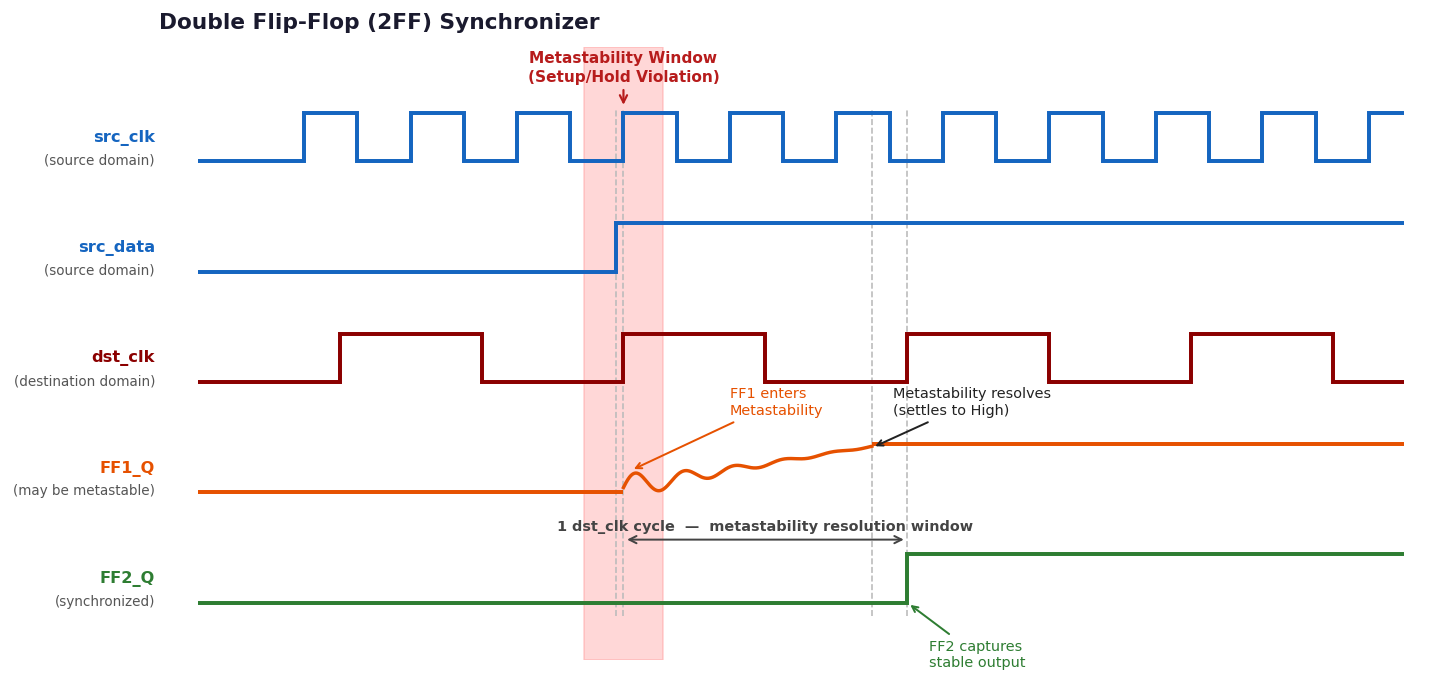
Figure 1: Double flip-flop synchronizer
The benefit over XPMs: it’s portable. A 2-FF chain works the same on Xilinx, Intel, Lattice, or anything else. The downside is that there’s no abstraction and an increased chance of an error or unoptimized design.
3.1 ASYNC_REG Attribute
ASYNC_REG must be applied to both synchronizer registers when doing manual CDC. Without it, Vivado treats them as ordinary registers and may optimize them in ways that break the synchronizer.
(* ASYNC_REG = "TRUE" *) reg ff1, ff2;

always @(posedge dst_clk) begin
    ff1 <= src_data;
    ff2 <= ff1;
end
Using ASYNC_REG:
-
Prevents optimization: Vivado won’t merge the two FFs into a single LUT or pipeline them in a way that removes the metastability resolution time.
-
Controls placement:
place_designlocates the FFs in adjacent slices, which keeps the interconnect delay short and improves MTBF. -
Enables CDC recognition:
report_cdcidentifies the path as a synchronized single-bit crossing instead of flagging it as No Synchronizer.
You still need to add set_max_delay -datapath_only on the CDC path manually. This tells Vivado to skip normal setup timing on it since the synchronizer handles the metastability, not the timing constraint.
4. The Single-Bit XPM CDC Decision Tree
This is the second option for CDC i.e. using XPMs. Before picking a primitive, there are two questions: is it a reset signal, and if not, is it a pulse? Resets need different handling from data signals because assertion and deassertion have different timing requirements. A pulse needs different handling from a level signal. UG949 Figure 86 shows this:
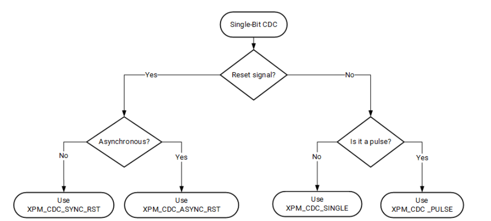
Figure 2: Single-bit CDC decision tree
5. XPM_CDC_SYNC_RST
Used to synchronize a reset to a different clock domain. Both assertion and deassertion are synchronous to the destination clock. INIT parameters sets the output of XPM at power-on i.e. before the input reaches the output through FF chain: INIT=1 means the design starts with flipflops initialized to 1, i.e. output will be 1, INIT=0 mean output will be 0.
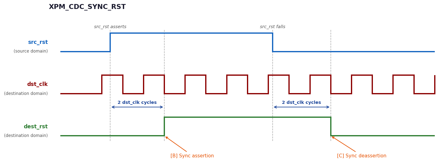
Figure 3: XPM_CDC_SYNC_RST, both assertion [B] and deassertion [C] are synchronized to dst_clk, each delayed by DEST_SYNC_FF cycles.
// xpm_cdc_sync_rst: Synchronous Reset Synchronizer
// Xilinx Parameterized Macro, version 2024.2

xpm_cdc_sync_rst #(
   .DEST_SYNC_FF(4),    // DECIMAL; range: 2-10
   .INIT(1),            // DECIMAL; 0=initialize synchronization registers to 0,
                        // 1=initialize synchronization registers to 1
   .INIT_SYNC_FF(0),    // DECIMAL; 0=disable simulation init values, 1=enable simulation init values
   .SIM_ASSERT_CHK(0)   // DECIMAL; 0=disable simulation messages, 1=enable simulation messages
)
xpm_cdc_sync_rst_inst (
   .dest_rst(dest_rst), // 1-bit output: src_rst synchronized to the destination clock domain.
                        // This output is registered.

   .dest_clk(dest_clk), // 1-bit input: Destination clock.
   .src_rst(src_rst)    // 1-bit input: Source reset signal.
);

// End of xpm_cdc_sync_rst_inst instantiation
5.1 Selecting DEST_SYNC_FF
DEST_SYNC_FF sets the number of metastability protection registers in the synchronizer chain. Higher values improve MTBF at the cost of latency and a few extra FFs. The right process for picking a value:
-
Step 1: Run the design through the full Vivado implementation flow.
-
7-series devices: Use the default
DEST_SYNC_FFvalue. It’s conservative and meets typical reliability requirements. For critical designs, do a proper MTBF analysis. -
UltraScale/UltraScale+: Run
report_synchronizer_mtbfafter implementation and iterate. IncreaseDEST_SYNC_FFif MTBF is too low, decrease it if you want to reduce latency or area. Figure 88 in UG949 shows the full flow.
The same process applies to manual CDC circuits where ASYNC_REG is correctly applied to all synchronization registers. It’s not XPM-only.
6. XPM_CDC_ASYNC_RST
An asynchronous reset needs to assert immediately i.e. you don’t want the design sitting in an unknown state while the reset propagates through a synchronizer pipeline. But deassertion (reset removal) needs to be synchronized to the destination clock. If reset deasserts asynchronously, different parts of the design may come out of reset on different clock cycles and that causes corruption.
XPM_CDC_ASYNC_RST handles this correctly:
-
Assertion: Immediate and asynchronous. The output asserts as soon as the input asserts, with no dependency on the destination clock.
-
Deassertion: Synchronous to the destination clock. Reset removal is synchronized through
DEST_SYNC_FFflip-flop stages.
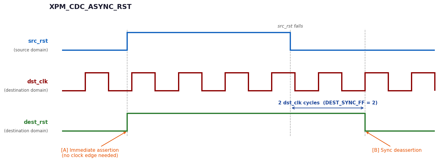
Figure 4: XPM_CDC_ASYNC_RST, assertion is immediate [A], deassertion is synchronized through DEST_SYNC_FF stages [B].
Why is INIT not present here? In XPM_CDC_SYNC_RST, both assertion and deassertion go through the synchronizer FFs, so their power-on state determines whether the design starts in reset i.e.INIT controls that. In XPM_CDC_ASYNC_RST, assertion bypasses the FFs entirely. The output is driven directly by the input, so at power-on, if the reset is asserted, the output is already asserted regardless of what state the FFs are in. INIT would have nothing to do on the assertion side, and by the time deassertion happens the FFs are already overridden by the active reset input.
// xpm_cdc_async_rst: Asynchronous Reset Synchronizer
// Xilinx Parameterized Macro, version 2024.2

xpm_cdc_async_rst #(
   .DEST_SYNC_FF(4),    // DECIMAL; range: 2-10
   .INIT_SYNC_FF(0),    // DECIMAL; 0=disable simulation init values, 1=enable simulation init values
   .RST_ACTIVE_HIGH(0)  // DECIMAL; 0=active low reset, 1=active high reset
)
xpm_cdc_async_rst_inst (
   .dest_arst(dest_arst), // 1-bit output: src_arst asynchronous reset signal synchronized to
                          // destination clock domain. This output is registered. NOTE: Signal
                          // asserts asynchronously but deasserts synchronously to dest_clk.
                          // Width of the reset signal is at least (DEST_SYNC_FF*dest_clk) period.

   .dest_clk(dest_clk),   // 1-bit input: Destination clock.
   .src_arst(src_arst)    // 1-bit input: Source asynchronous reset signal.
);

// End of xpm_cdc_async_rst_inst instantiation
7. XPM_CDC_SINGLE
This is the XPM equivalent of the manual 2-FF synchronizer. It handles a single-bit level signal crossing from one clock domain to another. Functionally it’s the same circuit, but with the XPM benefits e.g. ASYNC_REG handled automatically, recognized by report_cdc and report_synchronizer_mtbf, and DEST_SYNC_FF for tuning the number of sync stages.
SRC_INPUT_REG: Enable this when the input is driven by combinational logic rather than a registered output in the source clock domain. It adds a register on the input clocked bysrc_clk, so the signal is stable for at least one full source clock period before entering the synchronizer chain. This prevents combinational glitches from entering the first sync FF.src_clkonly needs to be connected when this parameter is enabled.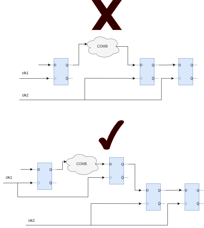
Figure 5: Proper CDC after combinational logic.
Why not use this for resets? XPM_CDC_SINGLE treats both edges the same — assertion and deassertion both travel through the synchronizer pipeline and are delayed by DEST_SYNC_FF cycles. For a reset, that’s a problem. You either need immediate assertion (async reset) or you need both edges handled synchronously (sync reset). XPM_CDC_SINGLE gives you the same behavior as XPM_CDC_SYNC_RST, but XPM_CDC_SYNC_RST is the better choice for a sync reset because it includes the INIT parameter, which sets the power-on state of the synchronizer chain before the reset signal propagates through it.
// xpm_cdc_single: Single-bit Synchronizer
// Xilinx Parameterized Macro, version 2024.2

xpm_cdc_single #(
   .DEST_SYNC_FF(4),    // DECIMAL; range: 2-10
   .INIT_SYNC_FF(0),    // DECIMAL; 0=disable simulation init values, 1=enable simulation init values
   .SIM_ASSERT_CHK(0),  // DECIMAL; 0=disable simulation messages, 1=enable simulation messages
   .SRC_INPUT_REG(1)    // DECIMAL; 0=do not register input, 1=register input
)
xpm_cdc_single_inst (
   .dest_out(dest_out), // 1-bit output: src_in synchronized to the destination clock domain.
                        // This output is registered.

   .dest_clk(dest_clk), // 1-bit input: Clock signal for the destination clock domain.
   .src_clk(src_clk),   // 1-bit input: optional; required when SRC_INPUT_REG = 1
   .src_in(src_in)      // 1-bit input: Input signal to be synchronized to dest_clk domain.
);

// End of xpm_cdc_single_inst instantiation
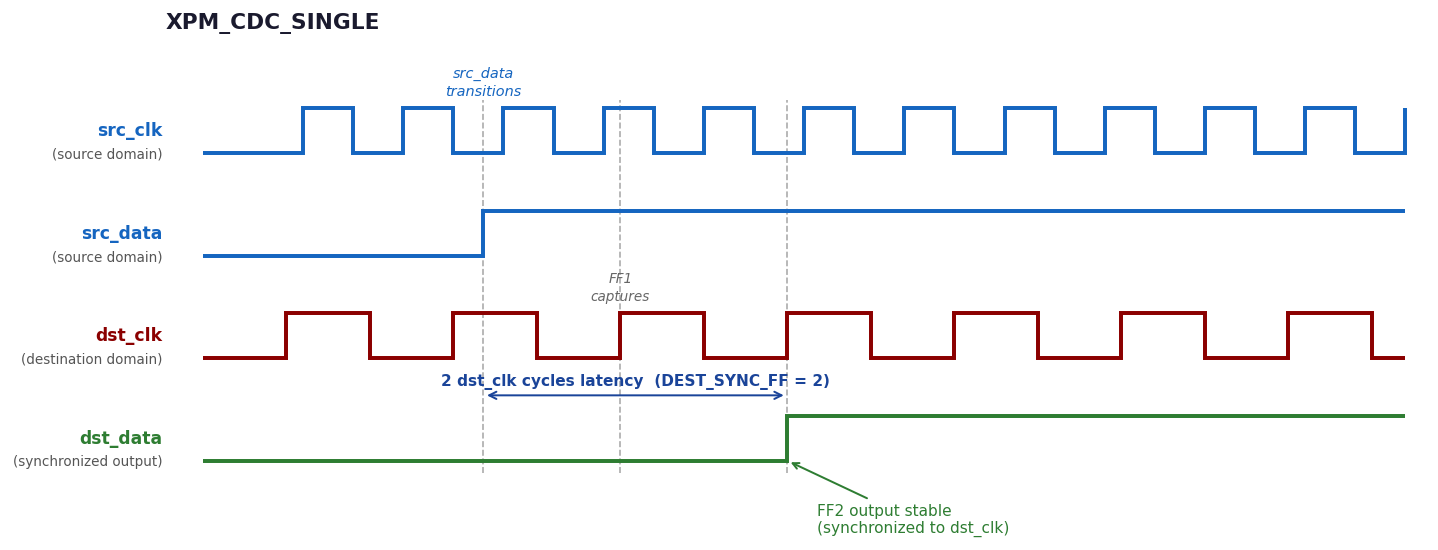
Figure 6: XPM_CDC_SINGLE
8. XPM_CDC_PULSE
For transferring a single-cycle pulse across clock domains. Internally it uses a toggle mechanism i.e. each source pulse flips a signal, that signal is synchronized to the destination clock, and the destination logic detects each toggle and converts it back to a pulse.
If the reset option is used, make sure no pulse is active during reset. Any pulse that occurs during reset will appear on the output after reset releases.
8.1 Minimum Pulse Gap
The minimum time between pulses (falling edge of pulse N to rising edge of pulse N+1):
gap > 2 × max(src_clk_period, dest_clk_period)
This is for the default DEST_SYNC_FF = 2. The toggle needs enough time to propagate through the synchronizer stages before a new pulse can be issued. With a larger DEST_SYNC_FF, the required gap scales up accordingly.
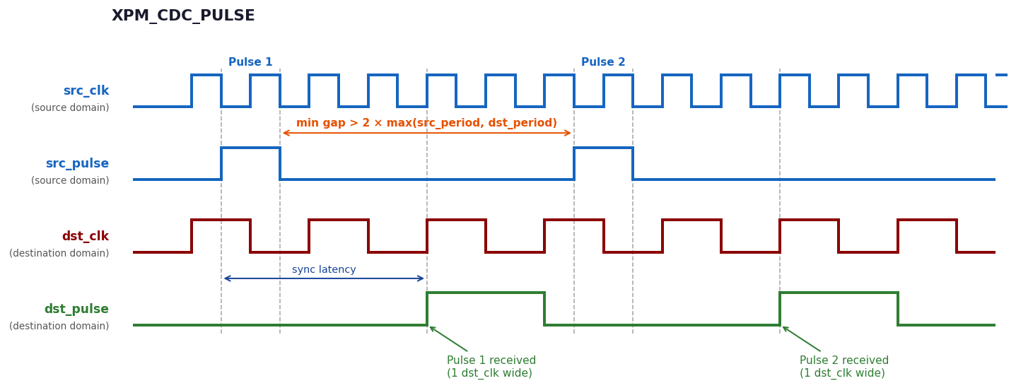
Figure 7: XPM_CDC_PULSE. Each source pulse generates a one-cycle pulse in the destination domain after sync latency.
// xpm_cdc_pulse: Pulse Transfer
// Xilinx Parameterized Macro, version 2024.2

xpm_cdc_pulse #(
   .DEST_SYNC_FF(4),   // DECIMAL; range: 2-10
   .INIT_SYNC_FF(0),   // DECIMAL; 0=disable simulation init values, 1=enable simulation init values
   .REG_OUTPUT(0),     // DECIMAL; 0=disable registered output, 1=enable registered output
   .RST_USED(1),       // DECIMAL; 0=no reset, 1=implement reset
   .SIM_ASSERT_CHK(0)  // DECIMAL; 0=disable simulation messages, 1=enable simulation messages
)
xpm_cdc_pulse_inst (
   .dest_pulse(dest_pulse), // 1-bit output: Outputs a pulse the size of one dest_clk period
                            // when transfer is correctly initiated on src_pulse input. This
                            // output is combinatorial unless REG_OUTPUT is set to 1.

   .dest_clk(dest_clk),     // 1-bit input: Destination clock.
   .dest_rst(dest_rst),     // 1-bit input: optional; required when RST_USED = 1
   .src_clk(src_clk),       // 1-bit input: Source clock.
   .src_pulse(src_pulse),   // 1-bit input: Rising edge of this signal initiates a pulse transfer
                            // to the destination clock domain. The minimum gap between each pulse
                            // transfer must be at the minimum 2*(larger(src_clk period,
                            // dest_clk period)).
   .src_rst(src_rst)        // 1-bit input: optional; required when RST_USED = 1
);

// End of xpm_cdc_pulse_inst instantiation
9. Constraining XPM CDCs
XPM CDC modules generate their own set_max_delay -datapath_only constraints internally. You don’t need to write them. This is one of the cleaner advantages of using XPMs — the constraints are built in and correct by construction.
Important: XPM CDCs are not compatible with set_clock_groups. set_clock_groups has higher precedence and silently overwrites the XPM’s internal set_max_delay -datapath_only constraints. If you apply set_clock_groups to a clock pair that an XPM CDC connects, the XPM’s timing constraints are gone and the CDC analysis breaks.
If your design needs set_clock_groups elsewhere, make sure it doesn’t cover the clock pairs used by XPM CDC instances. Use set_false_path or set_max_delay -datapath_only scoped to specific paths instead.
10. Conclusion
For single-bit CDC, the choice of primitive comes down to what you’re crossing. The decision tree is the right starting point — reset vs. data, async vs. sync, level vs. pulse. Each case has a primitive that handles it correctly. Using the wrong one either breaks the functional behavior or produces misleading tool reports that will surface as problems later.
If portability matters, the manual 2-FF synchronizer with ASYNC_REG works across any vendor. If you’re on Xilinx/AMD only, XPMs are the cleaner option — the constraints, placement, and tool recognition are all handled for you.
Series: Clock Domain Crossing (CDC)
Part Topic Part 1 Clock Types, Metastability & the Clock Interaction Report Part 2 The report_cdc Report Part 3 (this post) Single-Bit CDC Synchronizers Part 4 Multi-Bit CDC Synchronizers