Embedded Linux (Zynq SoC): Part 3 - Device Tree Overlay and UIO
This is Part 3 of the Embedded Linux (Zynq SoC) series. Read Part 1 and Part 2: Device Tree if you haven’t already.
Table of contents
- Introduction
- Block Diagram
- What is UIO?
- Interrupt Flow (Hardware to Userspace)
- What is a Device Tree Overlay?
- The Overlay
- The C Application
- On the Board
- Summary
- What’s Next
1. Introduction
In Parts 1 and 2 we have been through enough theory. Now it is time to do something practical. In this blog we will learn about device tree overlays: when and how to use them, what UIO is, when and how to use it, and walk through the steps with a final test on a Xilinx Zybo board.
In this example, we’ll build a simple GPIO peripheral connected to buttons on the board in the FPGA and access it from a userspace application without writing a kernel driver. The button presses will generate an interrupt which we will detect in the software.
To make that work we need three things:
- a device tree overlay so Linux knows the hardware exists,
- UIO so the registers and interrupts are exposed to userspace,
- and a simple C application that waits for button interrupts.
2. Block Diagram
Here is the Vivado block design used for this example.
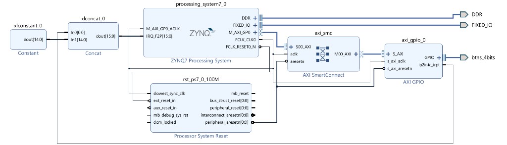
Figure 1: Zynq PS + AXI GPIO buttons, interrupt wired to IRQ_F2P.
What each block is doing (one line each):
- ZYNQ7 Processing System: Zynq PS (ARM cores + interrupt controller).
- AXI SmartConnect: AXI interconnect between the PS and the GPIO.
- AXI GPIO: memory-mapped GPIO for the buttons; also generates an interrupt when an input changes (PG144).
- btns_4bits: the four board buttons.
- Concat: packs the GPIO interrupt onto bit 0 of
IRQ_F2P. - Constant: ties the unused
IRQ_F2Pbits to 0. - Processing System Reset: reset for the AXI / PL logic.
The focus of this blog is UIO, device tree overlay, and interrupt handling, so we will not go into much detail about the FPGA design itself. You do not need this exact block design. Any AXI GPIO wired to a Zynq IRQ_F2P line works the same way. If you use a different PL interrupt pin, the device-tree interrupt number changes with it. For example, IRQ_F2P[0] becomes SPI 29 in the overlay, while IRQ_F2P[1] becomes SPI 30 (hardware IRQ 62, then 62 − 32, more detail on this in How the interrupt number is calculated).
Simply what this design does is:
- PS talks to AXI GPIO over AXI (read button state, enable interrupt registers).
- Button change →
ip2intc_irpt→ Concat →IRQ_F2P[0]→ GIC → Linux.
3. What is UIO?
UIO stands for Userspace I/O. It is a kernel framework including a kernel driver (uio_pdrv_genirq) which provides functionality like interrupt handling and MMIO access.
Normally, hardware peripherals are controlled by kernel drivers. But for simple FPGA IPs, writing a complete driver is often unnecessary. In many cases, you only need to:
- Access the peripheral’s registers.
- Receive an interrupt when an event occurs.
That’s exactly what UIO provides.
UIO divides the work between the kernel and your userspace application. The kernel handles tasks that require privileged access, while the application implements the device-specific logic.
Kernel (UIO driver)
- Claims and manages the interrupt.
- Creates the
/dev/uioXdevice. - Maps the peripheral’s registers so they can be accessed using
mmap(). - Wakes the application when an interrupt occurs.
Userspace application
- Opens
/dev/uioX. - Maps the peripheral registers with
mmap(). - Waits for an interrupt by sleeping on
read(). The process is free to work on other threads. - Processes the interrupt event.
- Clears the interrupt in the peripheral.
- Calls
write()to tell the UIO driver to re-enable future interrupts.
This split keeps the kernel driver generic and very small, while allowing the application to contain all of the device-specific functionality. Instead of writing a custom kernel driver for every simple FPGA peripheral, only the minimal interrupt and memory-management code runs in the kernel, with the rest of the logic implemented in userspace.
When should you use UIO?
UIO is a good choice when:
- Your peripheral is a simple memory-mapped (MMIO) IP.
- Most of the logic can live in a userspace application.
- You only need register access and basic interrupt handling.
If the hardware needs tight kernel integration, must be shared between multiple processes, or interacts with kernel subsystems such as networking or storage, then a full kernel driver is the better choice.
4. Interrupt Flow (Hardware to Userspace)
Why not just poll the GPIO data register in a loop?
- Polling wastes CPU time and still misses short presses unless you poll very fast.
- An interrupt wakes the CPU only when something actually happened.
So for a button, interrupt is the natural choice. AXI GPIO can raise ip2intc_irpt on every input change (press and release).
With UIO, the path from the FPGA pin to your app looks like this:
FPGA hardware
      |
      | IRQ signal
      v
UIO driver (kernel)
      |
      | wakes thread blocked in read()
      v
Your userspace application
What each step means:
- FPGA hardware: button edge hits AXI GPIO; the IP asserts
ip2intc_irpt, which is wired toIRQ_F2P[0]into the Zynq GIC. - UIO driver (kernel): the GIC delivers that IRQ to Linux and the registered UIO handler (
uio_pdrv_genirq) runs. It does not run your application logic in kernel space. It records that an interrupt happened and disables the IRQ line until userspace re-enables it. - Your userspace application: if your process was blocked in
read("/dev/uio0"), thatreadreturns. Your app wakes up, clears the hardware status in mapped registers, thenwrite()s back to UIO so the next IRQ can be delivered.
5. What is a Device Tree Overlay?
In Part 2, we learned that the device tree is loaded during boot and tells Linux what hardware is present on the board. Once the kernel has booted, that hardware description is fixed.
With PetaLinux, however, the FPGA can be reprogrammed while Linux is already running using the FPGA Manager and tools such as fpgautil. The new bitstream may introduce new PL peripherals, such as a custom AXI IP or GPIO, that were not present when Linux booted.
At this point, Linux has a problem. New hardware now exists on the FPGA, but Linux has no knowledge of it. It does not know the newly added peripheral’s address, interrupt, or which driver should manage it.
A device tree overlay solves this problem. It is a small device tree fragment that is applied on top of the existing device tree, adding or updating only the nodes needed for the newly loaded hardware. Instead of replacing the entire device tree, the overlay simply patches the parts that have changed.
Why not rebuild the entire device tree?
You certainly can. You could update the full device tree, rebuild the image, and reboot the system. However, for a small change in the FPGA design, this is unnecessary work.
A device tree overlay contains exactly the same information as a normal device tree node, such as compatible, reg, and interrupts, but only for the new hardware. This allows Linux to recognize and use the newly programmed FPGA peripherals without rebuilding or rebooting the system.
6. The Overlay
This is the overlay used for the button GPIO + UIO:
/dts-v1/;
/plugin/;

&amba {
    #address-cells = <1>;
    #size-cells = <1>;

    axi_gpio_uio@41200000 {
        compatible = "generic-uio";
        status = "okay";
        reg = <0x41200000 0x10000>;
        interrupt-parent = <&intc>;
        interrupts = <0 29 4>;
    };
};
/dts-v1/;: marks this as device tree source./plugin/;: marks this file as an overlay (not a complete tree).&amba { ... }: which parent node in the base device tree this overlay node belongs under. On many Zynq / PetaLinux trees the labelambapoints at/axi. Check your base DTS (or/proc/device-tree) for the real label; some trees use&axiinstead. Same idea for&intc: it must be the label of your GIC node in the base tree.#address-cells/#size-cells: must match the parent bus (usually<1>/<1>on Zynqamba/axi).axi_gpio_uio@41200000: new device node. The name before@can be anything sensible; the@41200000should match the MMIO base so the unit address stays consistent withreg.compatible = "generic-uio": which driver should bind. Here we want UIO (uio_pdrv_genirqwithof_id=generic-uio).status = "okay": this device is enabled.reg = <0x41200000 0x10000>: MMIO window: base and size from Vivado’s Address Editor. This is what userspace willmmapthrough UIO.interrupt-parent = <&intc>: interrupt controller is the Zynq GIC node already present in the base tree.interrupts = <0 29 4>: explained in detail below.
The base address and range come from Vivado Address Editor (Window → Address Editor), not from guessing:
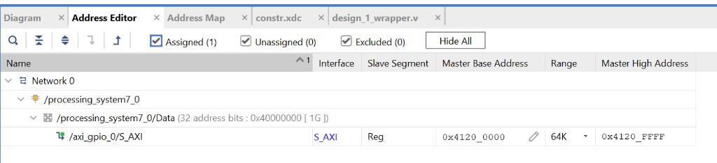
Figure 2: Address Editor, AXI GPIO mapped at 0x41200000, range 64K (0x10000).
Here Master Base Address is 0x41200000 and Range is 64K, which is 0x10000 bytes. That is why reg uses those two values even though the GPIO only has a handful of useful registers; the bus mapping is allocated in a 64K window. If your design shows a different base, put that base in both @... and reg.
Why reg if we only care about the interrupt?
- UIO uses
regto create the MMIO mapping for/dev/uio0. Without it there is nothing tommap, so userspace cannot touch the GPIO at all, not even to enable interrupts or read which button was pressed. - That same mapping is also how the app clears
IPISRafter each IRQ so the level interrupt can drop and the next press can fire again.
How the interrupt number is calculated (29 and the −32)
The line:
interrupts = <0 29 4>;
is three cells for a GIC:
| Cell | Value | Meaning |
|---|---|---|
| 1 | 0 |
Shared Peripheral Interrupt (SPI), not a PPI |
| 2 | 29 |
SPI index |
| 3 | 4 |
IRQ type: level-high (matches AXI GPIO ip2intc_irpt) |
The interesting one is 29. It does not appear directly in Vivado as “29”. You get it from the Zynq PL→PS interrupt map plus how Linux / device tree number GIC SPIs.
From the Zynq-7000 TRM (PL interrupt signals):
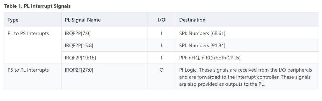
Figure 3: PL interrupt signals into the PS / GIC (Zynq-7000).
For our design we use IRQ_F2P[0] (also written IRQF2P[0]):
- Table row:
IRQF2P[7:0]→ SPI / IRQ IDs[68:61] - So bit 0 maps to hardware interrupt ID 61
- In general:
IRQ_F2P[n]→ hardware ID61 + nforn = 0..7
/proc/interrupts on Linux will also show 61 for this line once the overlay is applied. That is the GIC hardware ID.
Device tree does not put 61 in the second cell. For ARM GICs, the device tree SPI number is:
DT SPI number = GIC hardware IRQ ID − 32
So:
IRQ_F2P[0]  →  hardware ID 61
61 − 32    →  29
interrupts = <0 29 4>;
If the GPIO interrupt were wired to IRQ_F2P[1] instead, the hardware ID would be 62 and the overlay would use interrupts = <0 30 4>; (62 − 32 = 30). The rest of the node stays the same.
Where does the −32 come from?
The ARM GIC interrupt ID space is split into bands:
| ID range | Name | What it is |
|---|---|---|
| 0–15 | SGI | Software Generated Interrupts |
| 16–31 | PPI | Private Peripheral Interrupts (per CPU) |
| 32+ | SPI | Shared Peripheral Interrupts (shared across CPUs) |
SPI hardware IDs therefore start at 32. The device tree binding for the GIC does not store the full hardware ID in the SPI cell. It stores the SPI index: how far that interrupt is past the start of the SPI range:
SPI index = hardware ID − 32
         = 61 − 32
         = 29
Linux then turns that back into hardware ID 61 when it programs the GIC. That is why:
- the overlay says
29 /proc/interruptsshowsGIC-0 61
7. The C Application
Goal of the app:
- enable AXI GPIO interrupt
- block until a button IRQ
- print which button
- clear status and arm again
- ignore the release edge (AXI GPIO interrupts on press and release)
These are the AXI GPIO registers we care about (offsets from the IP base address):
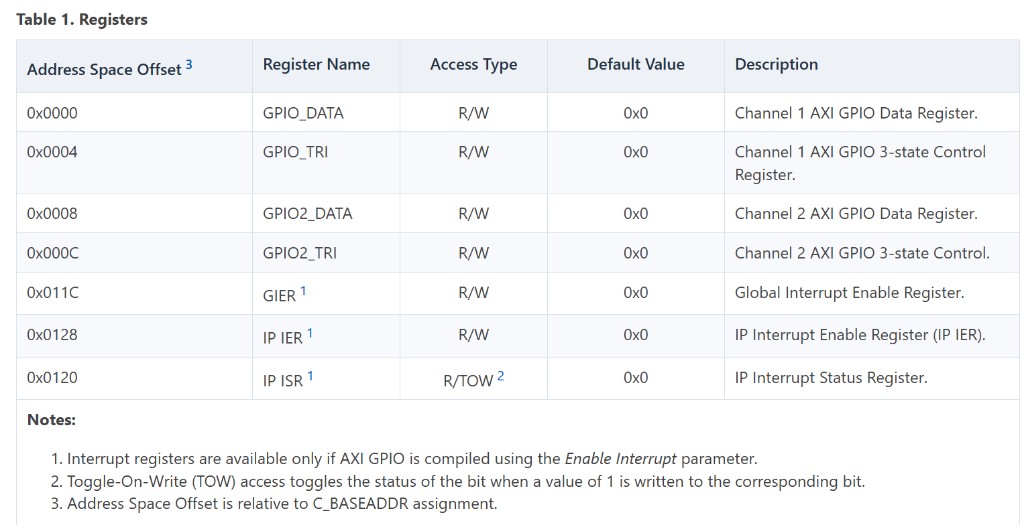
Figure 4: AXI GPIO register map.
Notes that matter for the app:
- Interrupt registers (
GIER,IP IER,IP ISR) exist only if Enable Interrupt was turned on in the AXI GPIO IP. IP ISRis toggle-on-write: writing1to a set bit clears that pending interrupt.- Offsets are relative to the base in
reg(0x41200000in our overlay).
Register offsets
#define MAP_SIZE   0x10000
#define GPIO_DATA  (0x000 / 4)
#define GPIO_GIER  (0x11C / 4)
#define GPIO_IPISR (0x120 / 4)
#define GPIO_IPIER (0x128 / 4)
The datasheet lists offsets in bytes (0x11C, 0x120, …). We map the registers as a uint32_t *, so each index steps by 4 bytes. Dividing by 4 converts a byte offset into an array index: gpioRegs[0x11C / 4] is the same as “base + 0x11C”.
MAP_SIZE matches the overlay reg size (0x10000).
Open UIO and map registers
int uioFd = open("/dev/uio0", O_RDWR);

volatile uint32_t *gpioRegs = mmap(NULL, MAP_SIZE,
    PROT_READ | PROT_WRITE, MAP_SHARED, uioFd, 0);
open: attach to the UIO device created when the overlay binds.mmap: map the GPIO MMIO window (0x41200000, size0x10000) into this process.- After this,
gpioRegs[offset]is a normal pointer read/write to PL registers.
Enable interrupts (GPIO + UIO)
uint32_t irqEnable = 1;

gpioRegs[GPIO_IPIER] = 1;          /* channel 1 IRQ enable */
gpioRegs[GPIO_GIER]  = 0x80000000; /* global IRQ enable */
gpioRegs[GPIO_IPISR] = 1;          /* clear any pending */

write(uioFd, &irqEnable, sizeof(irqEnable));  /* allow UIO to deliver IRQs */
AXI GPIO interrupt enables are two levels:
- IP IER (
0x128): per-channel enable inside the GPIO IP. Writing1enables channel 1 (the button channel in this design). If this bit is 0, a button edge does not set the IP interrupt output. - GIER (
0x11C): global interrupt enable for the whole IP. Bit 31 is the enable bit, so the value is0x80000000. If GIER is 0, no interrupt leaves the GPIO even when IPIER is set.
Without both, AXI GPIO never asserts ip2intc_irpt. Clearing IPISR drops any stale pending status before we start waiting. write() tells UIO it may deliver the next interrupt to userspace.
Main loop: wait, handle, re-arm
printf("Press a button...\n");
fflush(stdout);

while (1) {
    read(uioFd, &irqEnable, sizeof(irqEnable)); /* block until IRQ */

    gpioRegs[GPIO_IPIER] = 0;                   /* mask while bouncing */
    usleep(20000);

    uint32_t buttonValue = gpioRegs[GPIO_DATA] & 0xF;

    gpioRegs[GPIO_IPISR] = 1;                   /* clear HW status */
    gpioRegs[GPIO_IPIER] = 1;                   /* unmask GPIO IRQ */

    irqEnable = 1;
    write(uioFd, &irqEnable, sizeof(irqEnable)); /* re-enable UIO */

    if (buttonValue) {
        int i;
        for (i = 0; i < 4; i++) {
            if (buttonValue & (1u << i)) {
                printf("Button = %d\n", i + 1); /* bit0 -> 1 ... bit3 -> 4 */
                fflush(stdout);
            }
        }
    }
}
read: sleeps until the IRQ fires. Other threads can still run while this one blocks.- mask +
usleep: buttons bounce; briefly ignore extra edges. - read DATA: bitmask of which button(s) are down (
bit0= button 1, …,bit3= button 4). - clear IPISR: required for a level IRQ; skip this and you get an interrupt storm.
writeagain: UIO disables the IRQ when it fires; re-enable for the next press.if (buttonValue): press and release both interrupt. Idle is0, so print only on press. Each set bit prints asButton = 1…4.
Complete program (uio_btn.c)
#include <stdio.h>
#include <stdint.h>
#include <unistd.h>
#include <fcntl.h>
#include <sys/mman.h>

#define MAP_SIZE        0x10000

/* AXI GPIO register offsets */
#define GPIO_DATA       (0x000 / 4)
#define GPIO_GIER       (0x11C / 4)
#define GPIO_IPISR      (0x120 / 4)
#define GPIO_IPIER      (0x128 / 4)

int main(void)
{
    int uioFd;
    volatile uint32_t *gpioRegs;
    uint32_t irqEnable = 1;
    uint32_t buttonValue;

    /* Open the UIO device */
    uioFd = open("/dev/uio0", O_RDWR);

    /* Map GPIO registers into user space */
    gpioRegs = mmap(NULL, MAP_SIZE,
                    PROT_READ | PROT_WRITE,
                    MAP_SHARED,
                    uioFd,
                    0);

    /* Enable GPIO interrupts */
    gpioRegs[GPIO_IPIER] = 1;          /* Enable channel 1 interrupt */
    gpioRegs[GPIO_GIER]  = 0x80000000; /* Global interrupt enable */
    gpioRegs[GPIO_IPISR] = 1;          /* Clear pending interrupt */

    /* Tell UIO to enable interrupts */
    write(uioFd, &irqEnable, sizeof(irqEnable));

    printf("Press a button...\n");
    fflush(stdout);

    while (1)
    {
        /* Wait for an interrupt */
        read(uioFd, &irqEnable, sizeof(irqEnable));

        /* Disable interrupt while processing */
        gpioRegs[GPIO_IPIER] = 0;

        /* Simple debounce delay */
        usleep(20000);

        /* Read button state */
        buttonValue = gpioRegs[GPIO_DATA] & 0xF;

        /* Clear interrupt */
        gpioRegs[GPIO_IPISR] = 1;

        /* Re-enable GPIO interrupt */
        gpioRegs[GPIO_IPIER] = 1;

        /* Re-enable UIO interrupt */
        irqEnable = 1;
        write(uioFd, &irqEnable, sizeof(irqEnable));

        if (buttonValue) {
            int i;
            for (i = 0; i < 4; i++) {
                if (buttonValue & (1u << i)) {
                    printf("Button = %d\n", i + 1); /* bit0 -> 1 ... bit3 -> 4 */
                    fflush(stdout);
                }
            }
        }
    }

    return 0;
}
8. On the Board
Do these in order: load UIO with of_id, then program the bitstream, then apply the overlay, then run the app.
Compile the device tree overlay
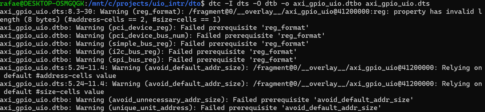
dtc -I dts -O dtb -o axi_gpio_uio.dtbo axi_gpio_uio.dts

Compile tip. #address-cells / #size-cells must match the parent bus. For Zynq amba / axi that is usually <1> and <1>. They are not strictly required for the overlay to work on the board, but if you omit them dtc falls back to defaults (#address-cells = 2) and you get reg_format warnings like these:
Copy axi_gpio_uio.dtbo onto the board.
Convert FPGA .bit to .bit.bin
fpgautil in newer versions of PetaLinux requires a .bit.bin version of bitstream instead of just .bit. This .bit can be converted to .bit.bin using the bootgen tool available in PetaLinux.
Create a .bif file first, add the following in this and save (replace the .bit name with your own bitstream file name:
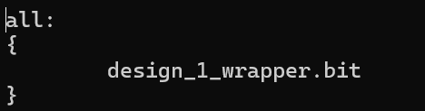
Run after sourcing PetaLinux:

Make sure the .bit file is present in same directory where the command is being run from.
Load the UIO driver
sudo modprobe uio_pdrv_genirq of_id=generic-uio
Why is of_id required?
Our overlay contains:
compatible = "generic-uio";
Normally, a kernel driver already contains a list of compatible strings that it supports that it matches with the compatible string in the device tree node. When Linux finds a matching node in the device tree, it automatically binds the driver.
But uio_pdrv_genirq driver is different. It does not hardcode any compatible strings. I’m not sure what the reason for this is. I think its just a design choice of author. So when loading the module you have to tell it which compatible string to look for in the dt node.
sudo modprobe uio_pdrv_genirq of_id=generic-uio

This tells the driver to bind to any device tree node whose compatible property is "generic-uio".
Check with lsmod (lists kernel modules that are currently loaded).
Apply the overlay
Load the bitstream:
sudo fpgautil -b <.bit.bin name>

Load the device tree overlay:
sudo fpgautil -o axi_gpio_uio.dtbo

Check the interrupt / device
ls -l /dev/uio0
grep axi_gpio /proc/interrupts
You should see something like:

Run the application
You can build the app with a PetaLinux C application recipe instead of calling the cross-compiler by hand. From your PetaLinux project:
petalinux-create apps --name uio-btn --enable
This creates the recipe under project-spec/meta-user/recipes-apps/uio-btn/. Replace the generated source (files/uio_btn.c) with your uio_btn.c, then:
petalinux-build -c uio-btn
The binary is under the PetaLinux build tree. Find it with:
find <plnx-proj-root>/build -name uio-btn -type f
With --enable, a full image build also installs it into the rootfs (usually as /usr/bin/uio-btn on the board).
You can also cross-compile on the host with the ARM cross compiler from PetaLinux, copy the binary to the board, then:
sudo ./uio-btn
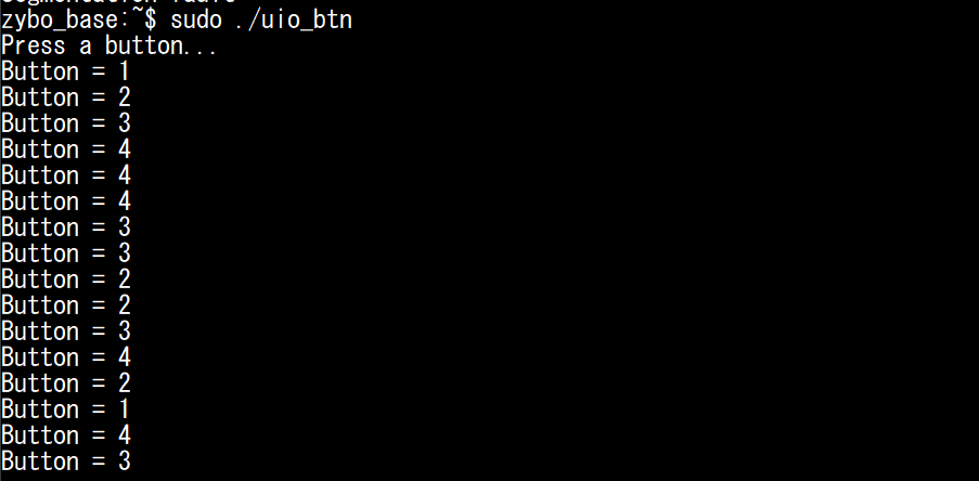
Press a button. You should get one line per press, for example:
9. Summary
- Vivado: buttons → AXI GPIO →
IRQ_F2P[0]. - Overlay: tells Linux the MMIO (
reg), the IRQ, andcompatible = "generic-uio". - Interrupt number: hardware ID
61→ DT SPI29because SPI IDs start at 32 (61 − 32). - UIO: kernel owns the IRQ line; your app owns the policy.
of_idmust matchcompatible, or the driver never binds.- App:
readto wait, clear GPIO status,writeto re-arm, ignore release.
In Part 2 the device tree described what exists. Here we showed how to add a PL peripheral at runtime and drive its interrupt from userspace.
10. What’s Next
Next we can look at doing the same path with a small in-kernel IRQ handler instead of UIO, and compare when each approach makes sense.
Series: Part 1 · Part 2: Device Tree · Part 3