Embedded Linux (Zynq SoC): Part 2 - Device Tree
1. Kernal’s board awareness
Part 1 introduced the device tree as the board-specific description the kernel needs. This part opens an actual tree and shows how it maps to the hardware.
While building the kernel, the user mainly provides two inputs: the cross-compiler and the kernel configuration.
Those steps decide:
Cross compilers provide information about architecture and ABI.
Kernel configuration decides which drivers and features are built into the kernel image.
After these steps are completed and the kernel is ready, it still does not know which peripherals exist on this board, or how they are wired. That missing description is what the device tree provides.
2. Why Can’t This Be Hardcoded in the Kernel?
You might think: the peripheral blocks on the chip are fixed, so why can’t that information just be embedded into the kernel itself? The reason is that the same SoC can be used on different boards, and those boards may use some of the available interfaces and leave others unused.
Example: same Zynq SoC, two different boards:
The SoC still has the same interfaces available. Board A connects UART0 and Ethernet (and may leave UART1 / SPI unused).
Board B connects UART1 and SPI flash instead, and leaves UART0 / Ethernet unwired.
The SoC is the same. But not all available interfaces are connected on the board.
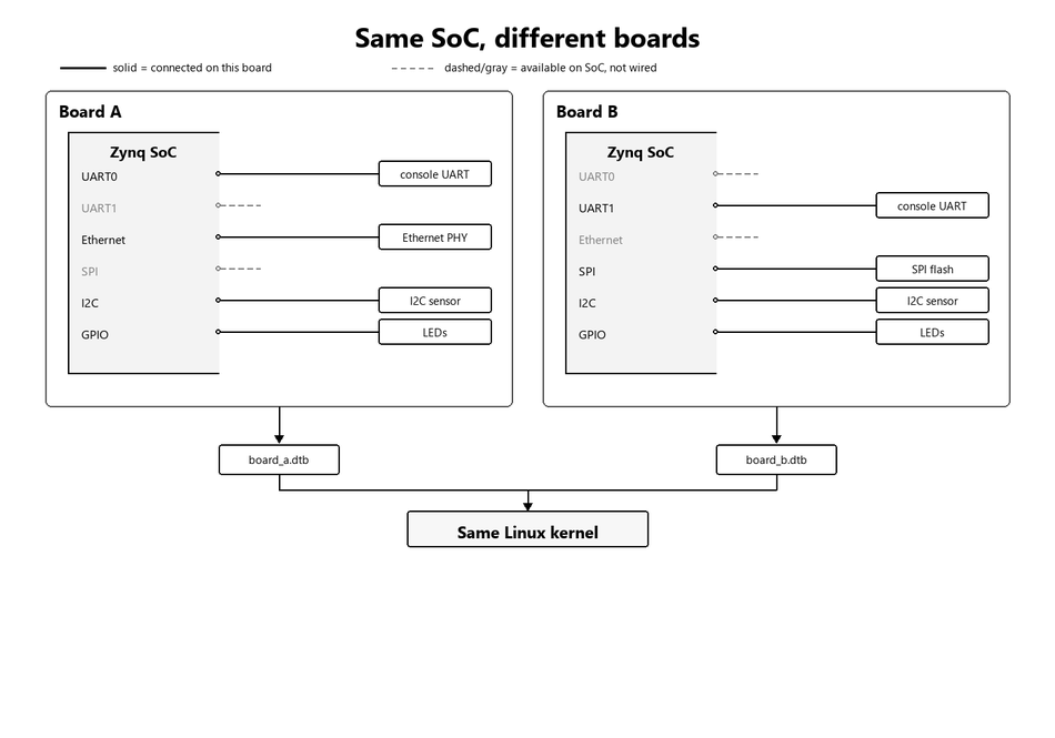
Figure 1: Same SoC interfaces on both boards; solid = wired on this board, dashed = available but not connected.
If every SoC interface is treated as present even when it is not wired on the board, drivers may probe hardware that is not there. That can mean failed probes, wasted resources, runtime failures, or in worse cases hangs and faults when a driver touches an address that is not valid for that board.
The other option is that each kernel is configured specifically for each different board. That’s how it was done before (board files / board-specific kernel setup). It worked, but every small board change meant editing and compiling the kernel again from scratch.
3. Device Tree
The solution is to separate the board description from the kernel itself using a device tree. A device tree is board-specific. This is how we tell a kernel built for the SoC family what is actually available on this board.
You can use the same kernel image with different boards that share the same SoC, just by replacing the device tree (the compiled DTB), as long as the needed drivers are still built into that kernel or available as modules. The DT describes only the hardware; the drivers still need to be present in the kernel for that hardware.
4. Device Tree Structure
A device tree is a hierarchy of nodes. The file always starts with a header, then a root node /, and then nested nodes under that root.
Here is a skeleton that shows the overall shape such as node names and hierarchy, with a few root properties shown:
/dts-v1/;

/ {
    model = "Example SoC Board";
    compatible = "vendor,board", "vendor,soc";

    #address-cells = <1>;
    #size-cells = <1>;

    chosen { };
    aliases { };

    cpus {
        cpu@0 { };
        cpu@1 { };
    };

    memory@0 { };
    reserved-memory { };

    axi {
        serial@e0000000 { };
        i2c@e0004000 { };
        my_ip@40000000 { };
    };

    fpga-region { };
};
How to read this structure:
/dts-v1/; marks the file as device tree source.
/ is the root node. It represents the whole board or platform and sits at the top of the hierarchy. Every other node is under it, directly or nested deeper.
Model and compatible: The model and compatible properties in the root node identify the board and SoC family, allowing the bootloader, firmware, and kernel to recognize the platform. The compatible property also appears in child nodes, where it identifies the specific hardware IP or peripheral. During boot, the Linux kernel compares this string against the list of devices supported by each driver and binds the matching driver to the device.
Address cells and size cells:
/ {
    #address-cells = <1>;
    #size-cells = <1>;

    memory@0 {
        reg = <0x00000000 0x40000000>;
    };
};
A cell in a device tree is always 32 bits (4 bytes). Therefore:
#address-cells = <1> means an address is written using one 32-bit cell. i.e. the address space is 32 bits
#address-cells = <2> means an address is written using two 32-bit cells (meaning the address space is 64-bit).
Similarly:
#size-cells = <1> means the size occupies one 32-bit cell.
#size-cells = <2> means the size occupies two 32-bit cells, i.e. the size cell is 64 bits. So its represented by 2 cells.
In the example above, the root specifies one address cell and one size cell, so the reg property is interpreted as:
reg = <address size>
Therefore,
reg = <0x00000000 0x40000000>;
means:
Start address: 0x00000000
Size: 0x40000000 (1 GB)
If instead the root used #address-cells = <2> and #size-cells = <2>, the same memory region would be written as:
memory@0 {
    reg = <0x00000000 0x00000000
           0x00000000 0x40000000>;
};
where the address and size are each represented using two 32-bit cells.
chosen: chosen holds boot arguments which are provided to the kernel during boot time.
aliases: aliases holds short names that point at longer node paths. This is just for readibitly and does not correspond to any hardware.
cpus: describes the CPU cores (cpu@0, cpu@1, …) This tells the kernel how many cores are available in the processor.
memory: describes system RAM available to the kernel.
reserved-memory: This lists memory regions that must not be used by kernel as normal RAM. This is for cases in which fixed large memory buffers are required such as in DMA buffers, framebuffers etc.
axi: axi groups peripherals reached through the AXI bus. PS(processor-system) Peripherals such as UART and I2C, and custom PL(programmable logic) IP nodes, are children of this node. This can also be named amba in some cases. In some device trees, amba and amba_pl is used to differentiate the peripherals connected to PS and PL respectively. This is just for device tree reprersenttion. this does not represent seperate axi buses for processor and FPGA
fpga-region: On many Zynq boards this node is an empty placeholder until FPGA manager is used which is for runtime conguration such as programming new bitstream at runtime..
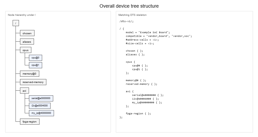
Figure 2: Overall device tree hierarchy and matching DT skeleton.
5. Parent and Child Relationships
A child node usually represents hardware that belongs to, or is accessed through, its parent. Two common cases:
Sub-system: hardware can have sub-components. For example, a processor can have multiple cores, so the cpus node contains all the CPU cores in the system.
cpus {
    cpu@0 { };
    cpu@1 { };
};
And a memory controller can have many memories:
memory-controller@e000e000 {
    compatible = "arm,pl353-smc-r2p1", "arm,primecell";
    reg = <0xe000e000 0x1000>;

    nand-controller@0 {
        reg = <0>; /* Memory Bank / Chip Select 0 */
    };

    flash@1 {
        reg = <1>; /* Memory Bank / Chip Select 1 */
    };
};
Bus connectivity: A bus node groups together all the peripherals that are accessed through that bus.
axi {
    serial@e0000000 { };
    spi@e0006000 { };
    gpio@e000a000 { };
};
6. MMIO
These peripherals use MMIO, which stands for memory-mapped I/O. Peripheral registers are mapped into the CPU address space. The driver talks to a peripheral by reading and writing these registers, not by driving individual I/O pins. That is why, in the device tree, we define each peripheral’s register space with reg, not its physical pins.
Example: reg = <0xe0000000 0x1000> → base 0xe0000000, length 0x1000 bytes.
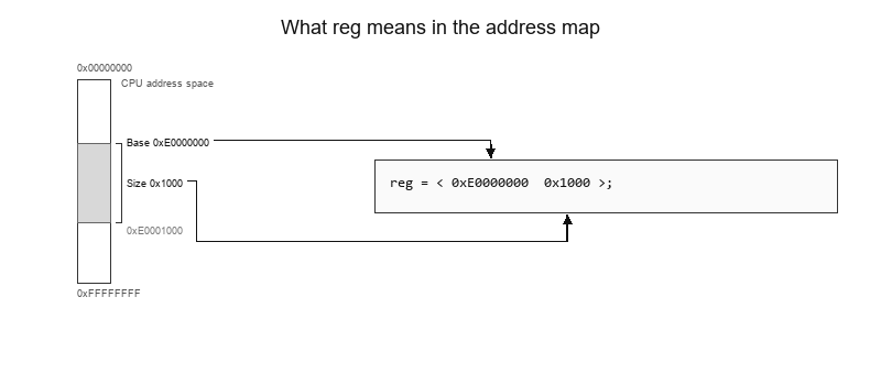
Figure 3: reg selects a slice of the CPU address map; base 0xE0000000, size 0x1000 bytes.
7. Example Peripheral node
Same UART with common properties:
serial@e0000000 {
    compatible = "xlnx,xuartps", "cdns,uart-r1p8";
    status = "okay";
    reg = <0xe0000000 0x1000>;
    clocks = <&clkc 23>, <&clkc 40>;
    clock-names = "uart_clk", "pclk";
};
What each one means:
compatible: tells which driver this peripheral uses.
reg: defines the register(MMIO) space.
status: “okay” vs “disabled”, meaning if this peripheral is connected on this board or not.
clocks: two values per clock entry: a phandle (see below) to a clock controller, and the clock ID within that controller.
Phandle: a pointer to another Device Tree node. It starts with &, like &clkc. Which means its referencing to another node named clkc.
Used when one node needs to point to another. For example clocks = <&clkc 23> means the UART uses clock 23 from the clkc node.
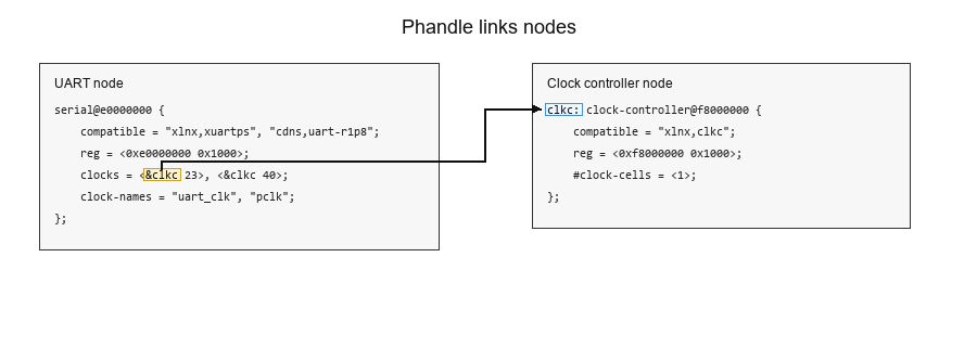
Figure 4: Phandle: &clkc in the UART node points to the clkc: clock-controller node.
Clock-names: these are the names that are defined in the kernel driver. They map one to one to the clocks, meaning uart_clk maps to <&clkc 23> and pclk maps to <&clkc 40>.
Why are there multiple clocks in this node?
Peripherals like UART keep CPU communication separate from the physical I/O of the peripheral.
For example, UART involves two separate communications:
- CPU ↔ UART registers: the processor reads and writes the peripheral’s register space.
- UART ↔ external world: the peripheral drives and receives signals on the wires.
These paths use different clocks:
- pclk (bus clock) runs the register interface for CPU access.
- uart_clk (functional clock) runs the internal logic, such as the baud-rate generator, that talks to the outside world. This idea is true for almost all external interfaces.
How clock-names Connects Driver and Device Tree
A peripheral driver defines the clock names it expects (for example, "uart_clk" and "pclk").
The Device Tree node for that same peripheral must list matching names in clock-names, in the same order as clocks. Those names map to the actual hardware clocks from the clock controller.
In the UART node above:
- first entry:
"uart_clk"→<&clkc 23> - second entry:
"pclk"→<&clkc 40>
When the kernel probes the driver, it reads the Device Tree node and matches by name:
- the driver asks for
"pclk"→ the kernel finds"pclk"inclock-namesand connects clock40 - the driver asks for
"uart_clk"→ the kernel finds"uart_clk"and connects clock23If the names do not match, the driver cannot get the correct clocks.
Second UART unused on this board:
serial@e0001000 {
    compatible = "xlnx,xuartps", "cdns,uart-r1p8";
    status = "disabled";
    reg = <0xe0001000 0x1000>;
};
In summary, the device tree tells the kernel a peripheral’s driver name (compatible), its register space (reg), whether it is enabled (status), and depending on the peripheral, some other peripherals like clocks, interrupts, and other resources.
8. How the Kernel Uses the Device Tree
At boot:
- U-Boot loads the kernel and the DTB into memory.
- The kernel starts at
/and walks the Device Tree. - For each node, it looks at
compatibleand finds a matching driver. - That driver’s
probefunction runs. probereads properties such asreg,interrupts, andclocks.- With that information, the driver can set up and run the peripheral.
9. What’s Next
In the next blog, we’ll create a Vivado design with an AXI based IP and then see how to add it in device tree.